Remote Flying Fish Project Part 16: 3D printing for propeller protector
Follow article Dave from DesignSpark
How do you feel about this article? Help us to provide better content for you.
Dave from DesignSpark
Thank you! Your feedback has been received.
Dave from DesignSpark
There was a problem submitting your feedback, please try again later.
Dave from DesignSpark
What do you think of this article?
In this chapter, we will learn how to use DesignSpark Mechanical to design the protector for the propeller by 3D printing technology.
The main idea of having a protector is to avoid potential damage induced by the propellers revolving at high frequency.
The reasons for using 3D-printing technology are:
- it is handy to use
- freeware is available on the Internet
However, it may take some time for the 3D printing machine to do its job before you can get your masterpiece out. And you may need to re-iterate the design procedures a few more times in order to optimize the shape and size to best fit the propellers and the PCB.
On the other hand, you may want to try using other materials (i.e. cardboard) if you don't have a 3D printer.
Before getting started, it is suggested to take a look at the merchandised protectors so that you can get inspired to design your own protector.
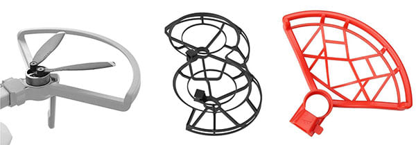
Do you see the similarities and differences?
THEY RESERVE AS MUCH SPACE AS POSSIBLE WHILE SETTING UP A BARRICADE BETWEEN THE PROPELLER AND OUTER ENVIRONMENT
Anyways, we should try to lower the weight of the protectors as much as possible or the fish balloon might sink too much.
---------------------------------------------------------------------------------------------------
First of all, you need to install the software in order to design your own 3D printing. In this project, we use DesignSpark Mechanical.

After creating a new project, you may see the following interface.

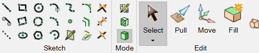
You may use the buttons on the up-hand side to draw lines, circles and curves.
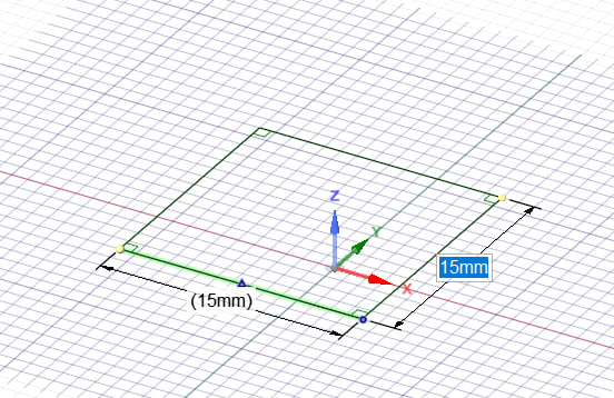
For example, you may use a line to draw a square. (Remarks: make sure you input a suitable distance, in this example, all lines are 15mm.)
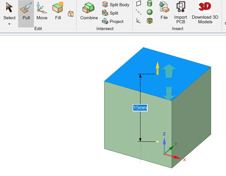
Then, you may use 'Pull" to create a cube.
Now, you may try to design your own protector. Here is a sample for reference with steps.
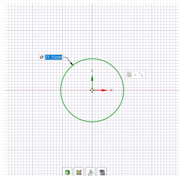
1. Create a circle. (base on the radius of your motors)
2. Create two rectangles.

3. Delete some of the lines.

5. Pull up for around 5mm.

6. Create five circles inside.

7. Pull down until it is empty.

8. Create two more circles outside.
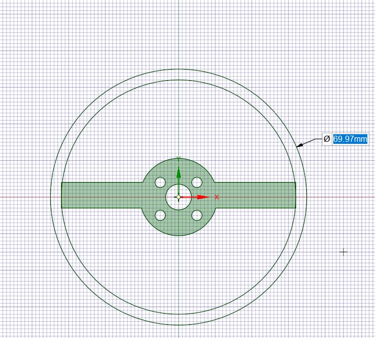
9. Draw two lines between two circles to separate them as below.
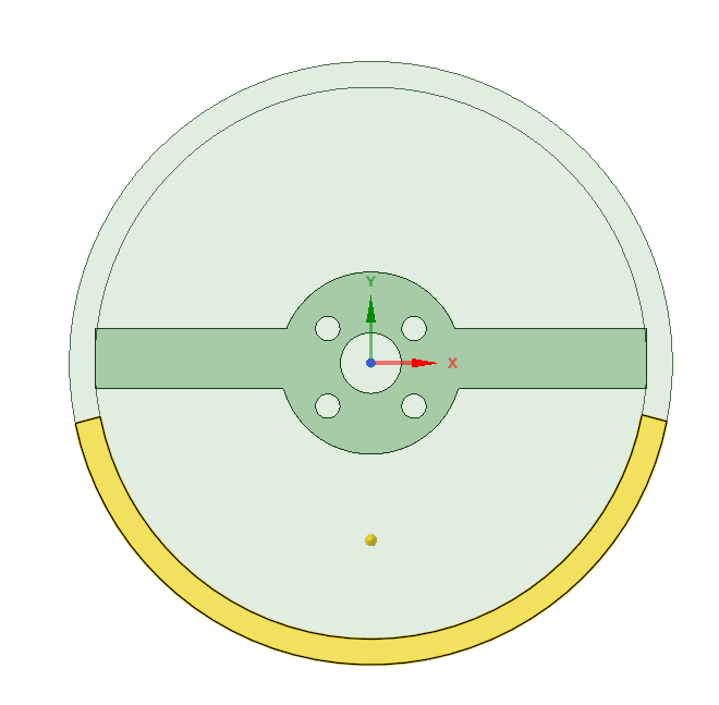
10. Pull up the longer shape around 16mm.

11. Delete the useless flats and draw two lines on the other side.

12. Pull down and remain around 4mm.

13. Finished.

You may refer to the post by Stuart Childs: https://www.rs-online.com/designspark/3d-printing-with-designspark-mechanical if you would like to learn more about DesignSpark Mechanical.
Hints:
1. The diameter of the hole for the motors > ~0.5mm of the diameter of the motor.
2. Be aware of the height of the protector, you may need to calculate the size of your motors after fixing it into the hole.
The last chapter is coming on the next: Flight Test and Fine-tunning.
Parts in this series
- Remote Flying Fish Project Part 1: Introduction
- Remote Flying Fish Project Part 2: DIY Series - Arduino Testing
- Remote Flying Fish Project Part 3: Motor Testing
- Remote Flying Fish Project Part 4: Bluetooth Testing
- Remote Flying Fish Project Part 5: Motor Testing with Remote XY
- Remote Flying Fish Project Part 6: PCB Design (preparatory)
- Remote Flying Fish Project Part 7: PCB Design (Schematic)
- Remote Flying Fish Project Part 8: PCB Design (PCB Layout)
- Remote Flying Fish Project Part 9: Soldering and Arduino Programming
- Remote Flying Fish Project Part 10: Flutter Introduction
- Remote Flying Fish Project Part 11: Flutter Installation on MacOS
- Remote Flying Fish Project Part 12: Flutter Installation on Windows
- Remote Flying Fish Project Part 13: Get yourself a Git
- Remote Flying Fish Project Part 14: Flutter UI Design
- Remote Flying Fish Project Part 15: Bluetooth in Flutter
- Remote Flying Fish Project Part 16: 3D printing for propeller protector
- Remote Flying Fish Project Part 17: Flight Test and Fine-tuning