Building a Connected Greenhouse - Part 2
Follow article
 Dave from DesignSpark
How do you feel about this article? Help us to provide better content for you.
Dave from DesignSpark
Thank you! Your feedback has been received.
Dave from DesignSpark
There was a problem submitting your feedback, please try again later.
Dave from DesignSpark
What do you think of this article?
Implementing monitoring and control with Python, MQTT and Node-RED
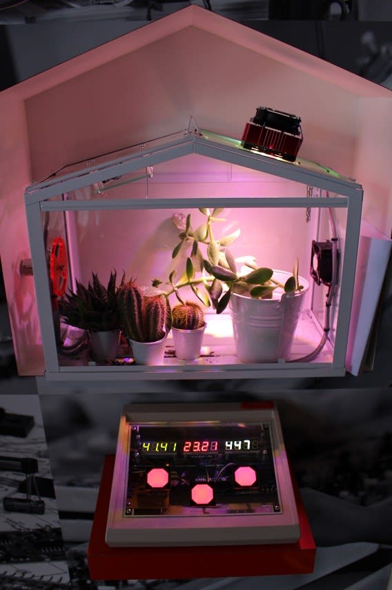
In Part 1 my colleague, Stuart, described how we were challenged with creating a connected greenhouse — integrating sensors and environmental controls, and that is visually engaging — before going on to introduce the main components and cover mechanical design. In this post I pick up where he left off and take a look at the electronics in more detail and software configuration.
Subsystems
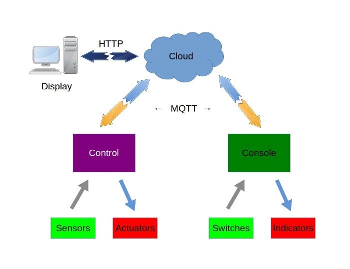
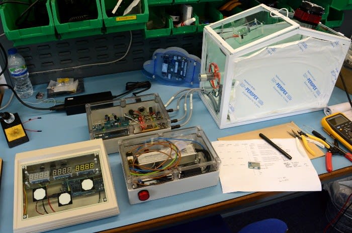
The overall system is comprised of a number of smaller subsystems. The greenhouse itself is equipped with sensors and actuators/outputs, which are connected to the Control unit.
The LED Driver houses a constant current LED power supply, which must have its 240V mains input — and not the low voltage output — switched. This is also cabled to the Control unit.
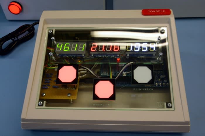
A sloped front desktop enclosure is fitted with 7-segment displays and capacitive touch switches, to provide the Console, which allows the environment to be monitored and manually controlled.
The Control and Console units both use MQTT messaging and this is brokered via the Cloud, a system configured such that there is no reliance on any external (Internet) services.
Finally, application logic can be viewed and configured via a web interface accessed using the Display system, an Intel Compute Stick PC running Ubuntu Linux.
Each subsystem is described in a little more detail below, with the main components listed, not including things like perf board, LEDs, resistors and connectors described in Part 1.
Sensors and actuators
-
HTU21D Click (862-4828) (temperature and humidity sensor)
-
BH1750 (124-6506) (light sensor)
-
IP68 DC tacho fan (914-4253) (ventilation source)
-
Motor and gearbox (298-5420) (vent)
-
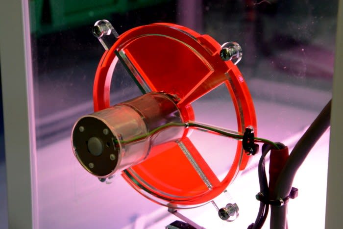
Petunia dev kit (875-0037) (LED illumination)
-
DC axial fan (878-1031) (LED module cooling)
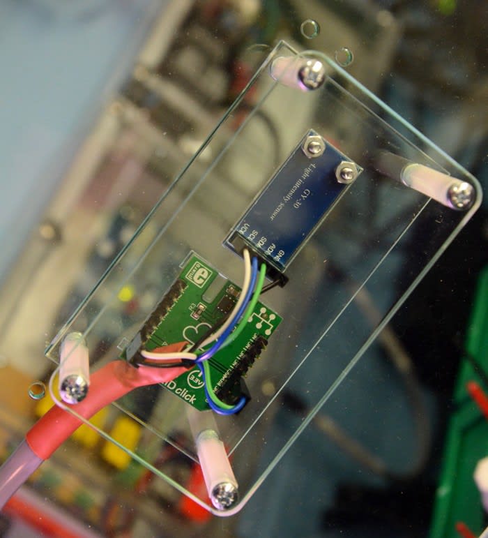
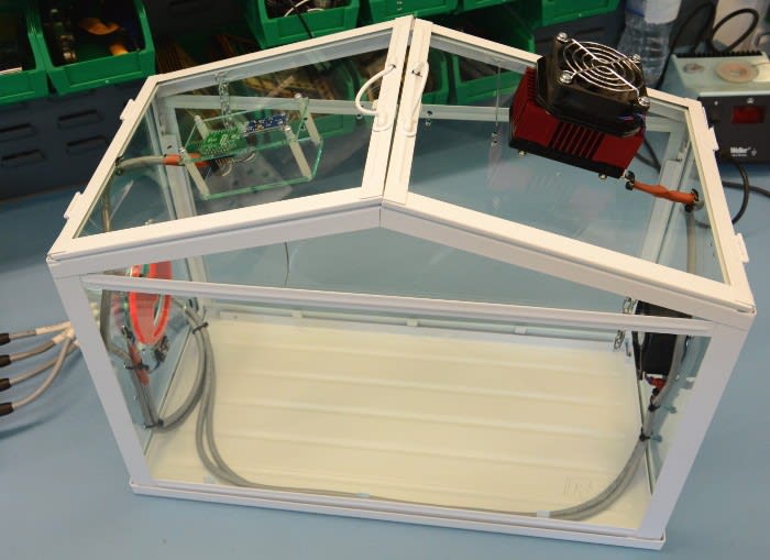
The HTU21D and BH1750 sensor modules are fitted to one of the greenhouse roof panels, with the temperature plus humidity sensor facing downwards, and the light sensor facing upwards. An IP68 rated 12VDC fan is used as a source of fresh air for ventilation, with a vent on the opposite end of the greenhouse for exhaust. The vent is rotated via a geared DC motor and the position is sensed via a cam plus microswitch. The horticultural LED module is fitted in the other roof panel and, while its heatsink should alone be sufficient, a fan is attached in order to keep it cool to the touch.
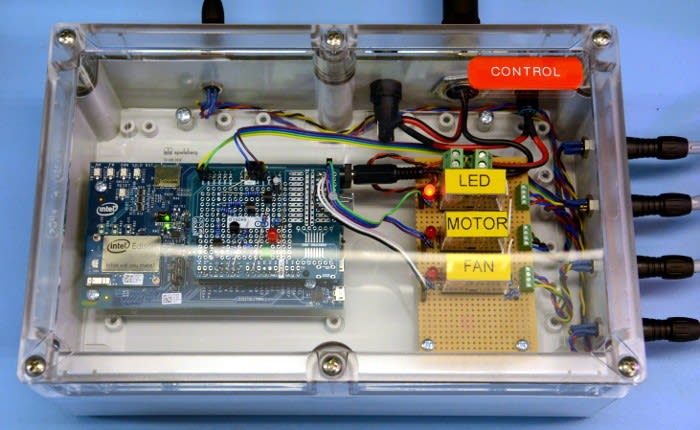
Control (sensor and actuator integration)
-
Intel Edison kit for Arduino (833-0895)
-
Arduino Proto Extension Kit (696-1677)
-
BC337 transistors (671-1116)
-
12VDC SPDT PCB mount relay
-
TIG IP67 enclosure (772-1000)
Intel Edison was selected as the embedded computing platform, since it provides a compact and yet reasonably powerful Linux system that is equipped with flash storage and wireless LAN, together with plenty of GPIO that can be easily accessed thanks to the Arduino breakout board.
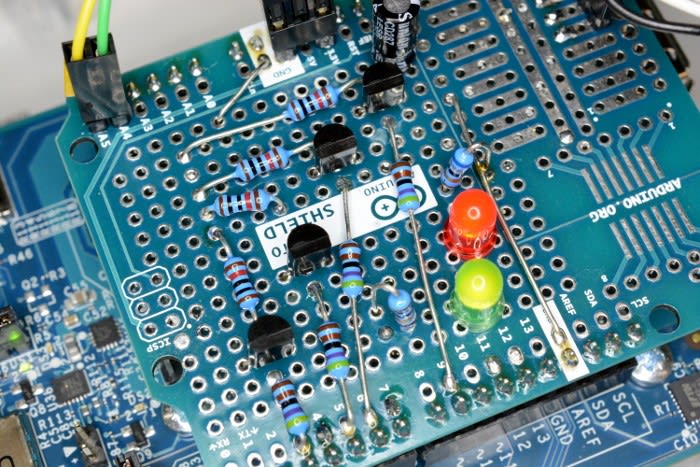
A simple circuit was constructed on an Arduino proto shield, with transistors being used to switch 12V to the coils of three relays. These relays in turn switch 12V to the LED Driver unit plus LED module cooling fan, the vent motor, and greenhouse ventilation fan. A fourth transistor is connected to a PWM output on the Edison to provide a speed control signal for the ventilation fan.
Vent position sensing is achieved via a cam and microswitch, with the latter connected to an input pin on the Edison, which is pulled to ground when the switch contacts are closed.
The temperature + humidity and light sensor boards are connected to the Edison via the I2C bus.
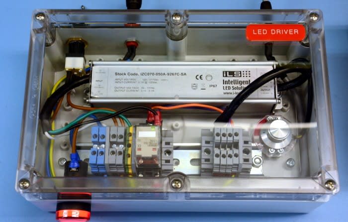
LED Driver
-
Key switch (711-8335)
-
Indicator LED Pilot Light (763-7946)
-
10A DPDT indicator relay 12VDC (488-1976)
-
DIN rail mounting relay socket (080-3376)
-
TIG IP67 enclosure (772-1000)
Since the LED driver is powered from a mains supply it was decided to house this in its own enclosure, with a relay to switch its input that takes a signal (12V) from the Control unit. As the Petunia LED module produces a rather intense light it was decided to also have a key switch for mains isolation and a large red indicator to show when this unit is powered up.
Console (sensor display and manual control)
-
Intel Edison kit for Arduino (833-0895)
-
Arduino Proto Extension Kit (696-1677)
-
BC337 transistors (671-1116)
-
Capacitive touch switches (904-2690)
-
Sloped front unshielded case (022-1027)
-
Adafruit 0.56” 4-digit 7-segment Display w/I2C Backpack
Once again an Intel Edison with the Arduino breakout board was used to provide an embedded computing platform. The capacitive touch switches are latching and provide control inputs for:
-
Mode: Automatic / Manual
-
Ventilation: On / Off (when in manual mode)
-
Illumination: On / Off (when in manual mode)
The touch switches also feature RGB LEDs which operate independently of the switch function. Here it was decided to use green to indicate automatic mode active and red for manual mode active. Since the LEDs require a little more current than the Arduino breakout can safely supply, these are again driven via BC337 transistors. The switches also output Vcc — 12V in this case — when active, so this was connected to the Arduino input pins via simple resistor voltage dividers.
The 7-segment LED modules are connected to the Edison I2C bus.
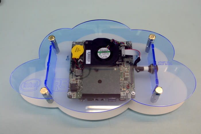
Cloud (application messaging and logic)
-
Intel Core i3 NUC (882-9691)
We're a big fan on the Intel NUC, since it packs a great deal of performance into a small package and particularly when you take advantage of M.2 SSD storage, removing the need for an external SATA drive. We've previously used Core i5 NUCs in a number of projects and even a Core i3 is almost certainly overkill here, but does gives us plenty of headroom.
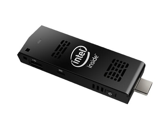
Display (application web interface)
-
Intel Compute Stick (882-9688) (Ubuntu)
-
Wireless keyboard and mouse (874-3963)
An Intel Compute Stick running Ubuntu Linux was selected as a neat solution for accessing the web interface which is used to monitor and configure the application. This can simply be mounted behind a HDMI monitor and is driven via a wireless keyboard and mouse.
Software
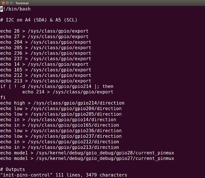
Part of the init-pins-control file
All of the subsystems run Linux and while you can use the Arduino IDE to write applications for the Intel Edison, we decided to use Python. We could equally have used one of a number of other languages also, such as JavaScript or native C.
The Intel Edison GPIO is multiplexed and the Arduino breakout board adds buffering and optional pull-up resistors, all of which are configured via the Linux GPIO sysfs interface, using the scripts init-pins-control and init-pins-console on the Control and Console systems respectively.
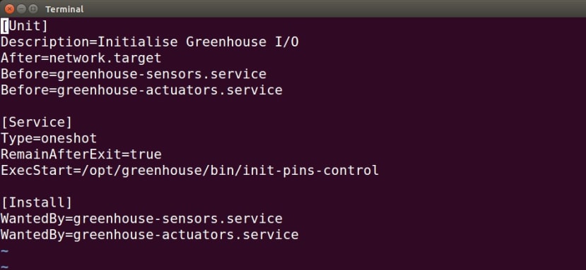
The pin initialisation scripts are executed upon start-up via systemd configuration in init-pins.service, with the example shown above for the Control system.
Control
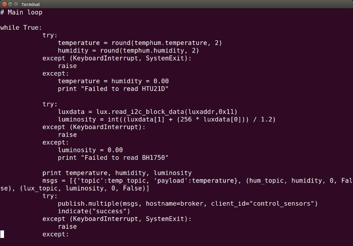
The Control system has two Python scripts: one that reads the sensors and publishes values to the MQTT broker, and another that subscribes to MQTT topics to receive control messages.
The main loop from the first of these, sensors-mqtt-pub, can seen above. This script reads the temperature + humidity and light sensors, publishing readings to the topics:
-
sensor/temperature
-
sensor/humidity
-
sensor/luminosity
If the script fails to read a sensor it publishes a value of 0.00 to the topic, so as to indicate failure. Whenever it succeeds in publishing a message, a red LED on the Arduino proto shield is flashed. If this LED stays permanently lit it means it has failed to publish.
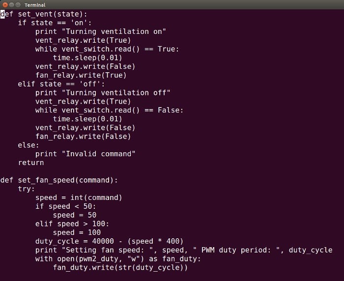
The second script, actuators-mqtt-sub, subscribes to MQTT and receives messages that turn the fan on/off and set its speed, open and close the vent, and turn the horticultural LED module off and on. A fragment of this can be seen above, showing the vent open/close function and part of the function which sets the fan speed. One of the great things about the Edison is that it has hardware support for PWM generation and configuring this is as simple as writing to files on the Linux filesystem.
The topics this Python script is concerned with are:
-
actuator/illumination
-
actuator/ventilation
-
actuator/fan_speed
Valid messages for the first two topics are “on” and “off”, with these turning the Petunia horticultural LED module on and off, and opening or closing the vent while also turning the ventilation fan on or off. The fan_speed topic takes a number between 50-100 for the fan duty cycle, with any number 100 setting it to 100%.
Every time the script receives a message a green LED on the Arduino proto shield is flashed. If this LED stays permanently lit it means it failed to subscribe.
In practice, if there was a problem publishing or subscribing to MQTT, it would tend to be a network issue or one with the MQTT broker itself, resulting in both LEDs remaining lit.
The two Python scripts are executed upon start-up by the greenhouse-sensors.service and greenhouse-actuators.service systemd configuration files, which ensure that they are only started after the appropriate GPIO pin initialisation shell script has been run.
Console
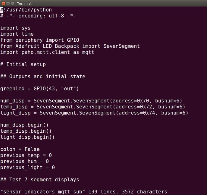
The Console runs three Python scripts and the first of these, sensor-indicators-mqtt-sub, subscribes to MQTT and receives sensor readings which are used to update the 7-segment LED displays.
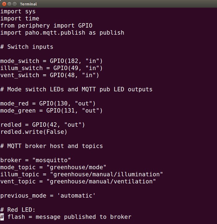
The second script, switches-mqtt-pub, reads the status of the three capacitive touch switches and publishes messages to the topics:
-
greenhouse/mode (“automatic” or “manual”)
-
greenhouse/manual/illumination (“on” or “off”)
-
greenhouse/manual/ventilation (“on” or “off”)
In addition to publishing to MQTT, this script sets the colour of the mode switch to red or green, depending on whether it's activated (manual mode) or not (automatic mode – default).
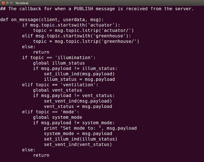
A third script, actuator-indicators-mqtt-sub, subscribes to the following MQTT topics:
-
greenhouse/mode
-
actuator/illumination
-
actuator/ventilation
The LEDs for the illumination and ventilation capacitive switches are lit if the Petunia LED module is commanded on or the ventilation is active. However, the colour they are illuminated with — green or red — is used to also indicate whether the system is in automatic or manual mode.
As with the Control system, green and red LEDs on the Arduino proto shield are used to indicate MQTT publish and subscribe success and failure. systemd is also once again configured via *.service files to start the Python scripts upon boot, but after GPIO pins have been initialised.
Cloud
The Cloud system is configured to run Ubuntu Linux and the following applications:
With MQTT configured, sensor readings can be published via the Control system, subscribed to via the Console and used to update the 7-segment LED displays. Capacitive touch switch state is also read and published to MQTT topics. However, there are no processes publishing to the MQTT topics which control the system outputs, i.e. ventilation (fan+vent) and illumination (LED module).
While we could have implemented control logic via the aforementioned Python scripts or additional ones, it was decided to do this instead via Node-RED, the visual tool for wiring the Internet of Things. Since this will keep the code which interfaces with the physical world — sensors and outputs — suitably simple, while also making it possible to very quickly prototype new logic and, should we wish, perform integration with other systems, thanks to the power of Node-RED.
Application flow
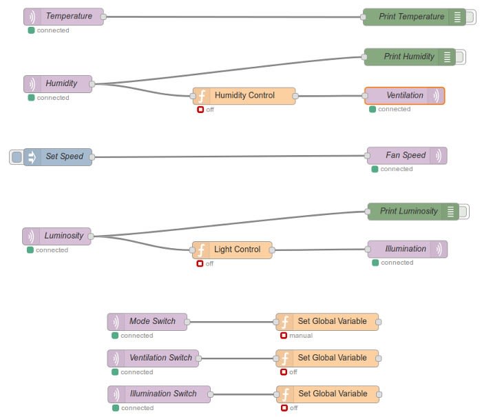
The full Node-RED flow can be seen above and in this we can see on the left-hand side that we subscribe to MQTT topics for Temperature, Humidity and Luminosity, along with topics for the status of the Mode Switch, Ventilation Switch and Illumination Switch.
One the right-hand side the flow publishes to MQTT topics for Ventilation, Fan Speed and Illumination.
Since we do not have any control over the greenhouse temperature, we simply connect this MQTT topic output to a debug node that allows us to print the messages received on the topic.
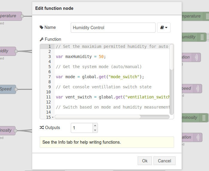
Messages received via the Humidity MQTT topic are input to a Humidity Control function. This is configured with a maximum permitted humidity, which if exceeded and the system is in automatic mode, will result in the ventilation being turned on by publishing “on” to Ventilation topic.
Similarly, light level readings are parsed by the Light Control function, which depending on these and once again the system operating mode, will emit an “on” or “off” message which is then published to the Illumination topic.
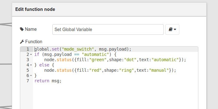
Down at the bottom of the flow we have three functions which set global variables to reflect the state of the capacitive touch switches. If the system is in manual mode, then the Humidity and Light Control functions will ignore sensor readings and use capacitive switch status to determine whether ventilation and illumination should be turned on or off.
Note also that each function has an additional few lines of code which update a status indicator, with a dot indicating automatic mode and a circle indicating manual, and red for that output being off and green indicating that it is on. For example, a green circle under the Humidity Control function means that the system is in automatic mode and ventilation is active.
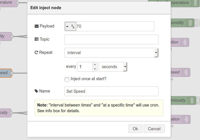
Finally, ventilation fan speed is set via an Inject node, which allows a payload to be configured — in this case the fan duty cycle — which is then published to the actuator/fan_speed topic.
Possible improvements
Now that we have ventilation and illumination controlled via Node-RED, with data available from temperature, humidity and light sensors, we could very quickly change the application logic and/or integrate other systems, e.g. via web APIs, to implement more advanced features.
One obvious enhancement would be to, rather than simply switch the ventilation fan on and off, speed up and slow down the fan motor as humidity increases and decreases. And to add temperature control would simply be a matter of additional simple circuitry for switching a heater, via another relay or perhaps via a remote control mains switch.
We could easily graph sensor measurements and control outputs, add e-mail notifications and much more... The list is of potential improvements is endless.
Summing up
This has been a fun project to work on and hopefully demonstrates how simple Python scripts can be used together with a versatile platform such as the Intel Edison, to quickly integrate sensors and outputs. Using MQTT as the “glue” to expedite the development of distributed systems, with rapid development of control logic and potential integration of more advanced features via Node-RED.
The design files for the custom acrylic components can be found, together with the shell and Python scripts, in the project GitHub repository.