Blind Control Using IOT- Designing and Enclosure with DSM (Part 3)
Follow article
 Dave from DesignSpark
How do you feel about this article? Help us to provide better content for you.
Dave from DesignSpark
Thank you! Your feedback has been received.
Dave from DesignSpark
There was a problem submitting your feedback, please try again later.
Dave from DesignSpark
What do you think of this article?
This is part three in a series of articles where I will be showing you how to create a home automation system using Components and hardware which can be purchased from the RS Components website- Part One - Part Two
Designing an enclosure with DesignSpark Mechanical
To start off with DesignSpark Mechanical (DSM), download and install the software. Open the software, go to File > New > Design


At this page, you can start your own design. For example, I designed an enclosure for my circuit and motor.
For more information on how to use the software, you can go through the tutorials or alternatively search for video examples online.
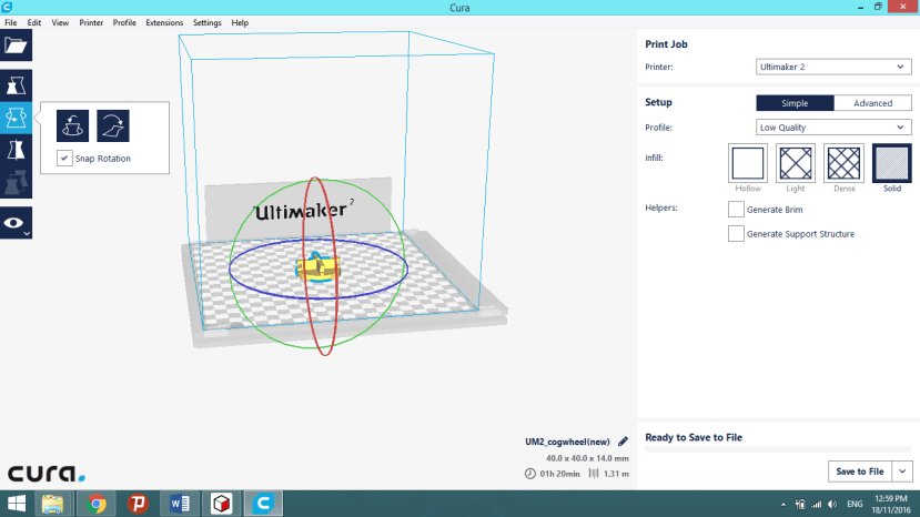
I’m going to show you how I constructed the cogwheel, I.E, the wheel/gear I use to reel the beads on. I designed these with the software and printed these using the Ultimaker2


First I select a circle and plot the circle on my sketch entering the diameter I want, which in this case. is a 4cm circle, thus its 40mm as shown below.

To make it 3-dimensional, all you have to do is select the function “Pull” under the edit ribbon and select the plane you want to pull. In my case, I want to give my circle a height, thus I just pull upwards and enter the height in millimetres and hit enter.

Now I have a disc made from a circle. Isn’t that cool! Next up, I’m going to draw “teeth” for the beads to catch on. So, I drew 2 long rectangles from north to south and the other from east to west which results in this:

Any line can be trimmed away with the trim tool located in the sketch ribbon.

I pull the surface up to create the area in the red boxes for the “teeth” or slots.


Slots are created by squares drawn on the surface and “Pull” to take that section away.

And now, I have my cogwheel with the slots to hold the beads.
The rest of the pictures below are the box and cover.


This is the enclosure I constructed using the software, which will be used to contain the Arduino Uno Wifi, Adafruit motor shield and the motor. The slits are for the Arduino ports and for better ventilation, so the heat won’t be trapped in the box. Two large slits starting from the brim to the middle are for the cord/ beads to pass through. There’s also a motor platform so that the motor will not shift and will be much more stable.

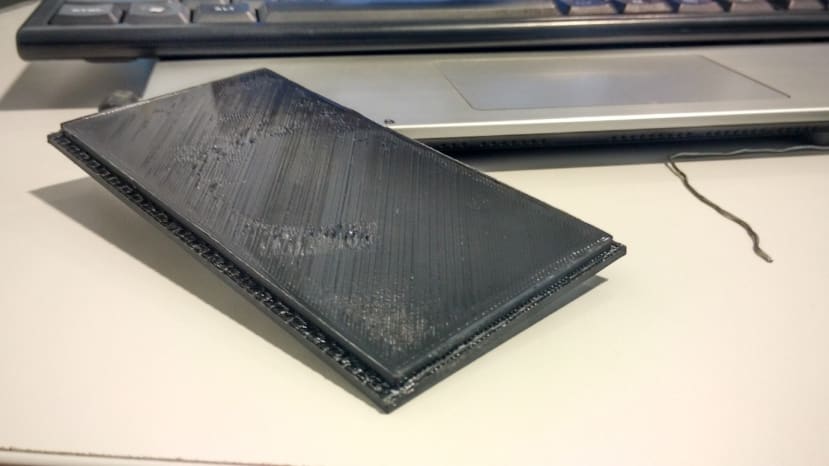
Above is the finished product printed by the Ultimaker2
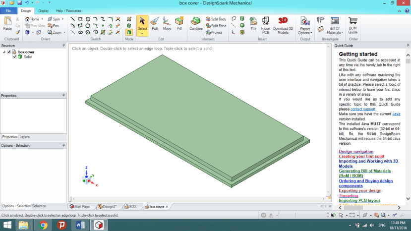
Here’s the cover for the box
The application I’m using to print these prototypes is Cura and with all my products I give them a low quality and solid infill (highlighted in red box) to ensure the parts don’t fall apart during operation and are rigid enough to handle stress.
Here a video showing an overview of the project.