Design a Bench Press Analyzer
Follow project
 Dave from DesignSpark
How do you feel about this article? Help us to provide better content for you.
Dave from DesignSpark
Thank you! Your feedback has been received.
Dave from DesignSpark
There was a problem submitting your feedback, please try again later.
Dave from DesignSpark
What do you think of this article?
 The bench press analyzer can be perfectly fixed on the barbell, detect the balance and motion range of bench press and feedback via LCD screen, LED blinking and buzzer beeping.
1. Motivation:
I am an amateur bodybuilder and I notice that quite a lot of people have their barbell leaning to one side when doing bench press. This widespread problem even occurs on experienced bodybuilders and is unfortunately hardly noticed by themselves.
A bench press analyzer can tell people whether they have unbalanced strength development when doing bench press. Also, it can provide rotation information about the bar caused by failure of trainer's wrists which should not happen in a proper movement. And it’s able to not only count repetition, but monitor and analyze whether the rep is too quick or too slow. By fixing the equipment at the middle of the barbell, it can remind the trainer about their movements by beep sound and clear information on LCD.
2. Components:
- Arduino UNO

- ADXL335 Accelerometer Board

- VL6180X Distance Board

- Nokia 5110 (LCD-10168)
- Battery and Battery Holder Case with w/DC Jack for Arduino
- Buzzer
- LEDs, Resistors, Triode, Buttons
3. Detailed System Diagram

4. Design Process
1). Pin Mapping
Because of some pins with special functions, it’s better to arrange pins from ones with complex function to normal GPIO. According to sensors and components I choose, the 3-axis accelerometer needs 3 pins with ADC input function. The distance sensor needs a pair of pins with I2C protocol. LCD screen needs a set of pins with SPI protocol. (It’s also possible to apply any pin for software SPI with relatively slow transmission speed.) Last but not the least, the buzzer needs a pin with PWM function.
The following table is the final pin mapping.
|
Master Pin |
Slave Pin |
||
|
Pin (Digital) |
Pin (AVR) |
Function |
|
|
0 |
PD0 |
RX |
NC |
|
1 |
PD1 |
TX |
NC |
|
2 |
PD2 |
GPIO |
LED LEFT |
|
3 |
PD3 |
PWM |
BUZZER |
|
4 |
PD4 |
GPIO |
LED RIGHT |
|
5 |
PD5 |
GPIO |
LDC DC |
|
6 |
PD6 |
GPIO |
LDC RESET |
|
7 |
PD7 |
GPIO |
LCD SELECT |
|
8 |
PB0 |
GPIO |
NC |
|
9 |
PB1 |
GPIO |
LCD BACKLIGHT |
|
10 |
PB2 |
SPI SS* |
RESET BUTTON |
|
11 |
PB3 |
SPI MOIS |
LCD DATA IN |
|
12 |
PB4 |
SPI MISO* |
BACKLIGHT BUTTON |
|
13 |
PB5 |
SPI SLK |
LCD SLK |
|
14 |
PC0 |
ADC0 |
ADXL335 X |
|
15 |
PC1 |
ADC1 |
ADXL335 Y |
|
16 |
PC2 |
ADC2 |
ADXL335 Z |
|
17 |
PC3 |
ADC3 |
NC |
|
18 |
PC4 |
I2C SDA |
VL6180 SDA |
|
19 |
PC5 |
I2C SCL |
VL6180 SCL |
* Although Nokia 5110 only requires MOSI and SLK in a set of SPI pins, it’s better to keep corresponding MISO and SS pin unused. However, on account of running out of pins, I use these two pins as GPIO. As a result, I have to use software SPI for LCD screen.
2). Initialize ADXL335 and VL6180 on Arduino UNO
For ADXL335, I connect X-axis to Arduino A0. It’ s easy to print ADC input data on serial monitor. Check the ADC data when ADXL board is placed horizontally and vertically from 2 sides and do linear calibration with 0°, 90° and -90° to get the calibration expression which can convert any data we get into leaning degree. Because trainers are not able to focus on reading accurate degree change and doing heavy bench press simultaneously, it’ s better to adjust the data’s precision to 1° or 2°.
For VL6180x, I call the ‘Adafruit_VL6180X.h’ library and get the range data on serial monitor.
3). Initialize LCD screen and other components
Connect LCD with Arduino UNO and call ‘Adafruit_GFX.h’ and ‘Adafruit_PCD8544.h’ library. Try to use its function print strings on LCD screen and print the data you get from sensors on screen.
For buzzer, I use tone() and noTone() functions to control it. Whenever the device moves into a position which is less than 50mm from trainer’s body, the buzzer beeps with parameter ‘count’ plus 1 on LCD screen meaning a rep of full-range motion done. Otherwise, the buzzer stays quiet. The figure below is the buzzer control circuit.

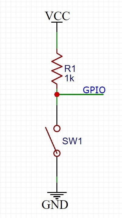
For reset button, whenever trainers want to start a new set of bench press, pressing that button will reset the ‘count’ on LCD to 0 without restart the device. Also, to prevent balance initialization error, reset button can also be used to reset the degree before training.
LCD backlight control button is used to turn on and off LCD backlight.
The figure below is the button circuit.
For the two LED, when the leaning degree is less than 15°, both LED are off. When the degree is from 15° to 40°, the LED on the leaning side is blinking. When the degree is larger than 40°, the LED on the leaning side is on.
4). Soldering components on a board.
Considering simplifying the circuit and stabilize the connection. I solder two sensors, buzzer, buttons and related control circuit on a board. And I also solder headers on it to connect with Arduino.
The figure below is the board.

5). Design device case
The device case is mainly used to contain 4 parts: Arduino UNO, the board with sensors and buttons, LCD screen and battery case. Thus, there are several requirements when design the case.
a). The board with sensors should face down so that it can test the range from trainer to the device.
b). LCD screen should face toward the front with LEDs so that the trainer can check the information on screen.
c). The structure of the case under the bar should be as thin as possible. Otherwise, it may effect full range motion of the bar.
d). The whole case should be fixed on a bar with 28mm diameter. Also, it should be easy to assemble and disassemble.
e). The battery case is relatively heavy, so it’s better to keep its center right above the bar to prevent unexpectable rotation of the case.
The figures below is the structure I design with DesignSpark Mechanical.

First, fix two axes on the bar.

Then, fix the main case on the axis and fix the battery on the main case.

The DSM file of the whole case is attached below for those interested.
6. Design the PCB board
Here I assemble all the components except Arduino and LCD screen on a PCB board. It’s an Arduino hat board with header directly fit into Arduino UNO. It also has header out to connect LCD screen. The step below is the what I design in DesignSpark PCB.
First, check ADXL335’s datasheet and create its circuit schematic.

Then check VL6180’s datasheet and create its circuit schematic. Here I use a LDO to convert Arduino’s 5v to 2.8V which the chip requires.

I assemble all the other components on this main schematic below. When placing all these headers on PCB board, make sure you check the position of corresponding headers on Arduino so that two boards can fit each other. And there is no main and sub schematics in DSPCB, so you need to use same net name to build connections between schematics.
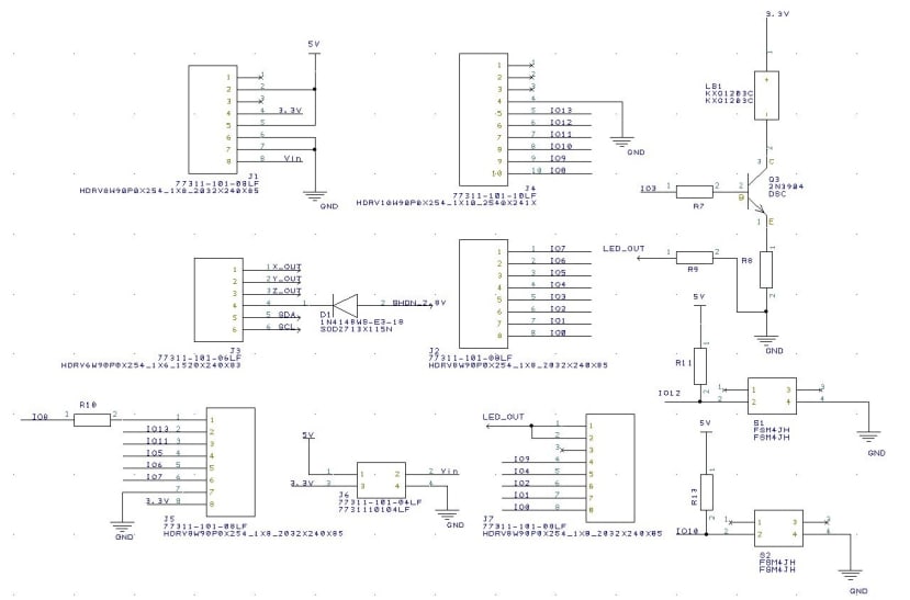
The figure below is what I route on PCB.
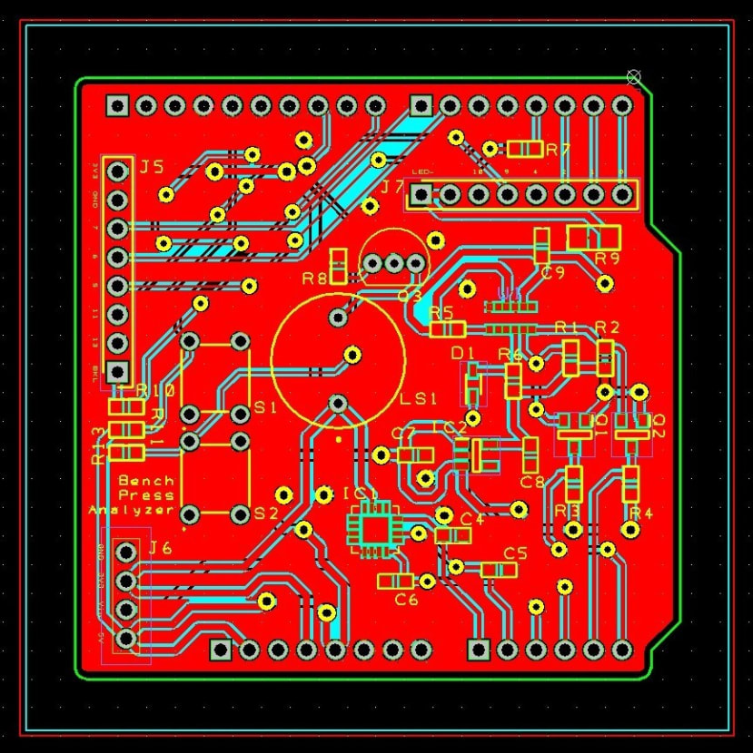
And the 3D view.

For timing reasons, I haven't fabricated PCB board in this project. The DS PCB project file I built is attached below for someone interested in building PCB version of this project.
Attention: It's better to turn off the device after using. Low battery power will cause self restart of the device.