AQ Project How to Part 1: AQ Sensor Kit Build Guide - ESDK
Follow article
 Dave from DesignSpark
How do you feel about this article? Help us to provide better content for you.
Dave from DesignSpark
Thank you! Your feedback has been received.
Dave from DesignSpark
There was a problem submitting your feedback, please try again later.
Dave from DesignSpark
What do you think of this article?
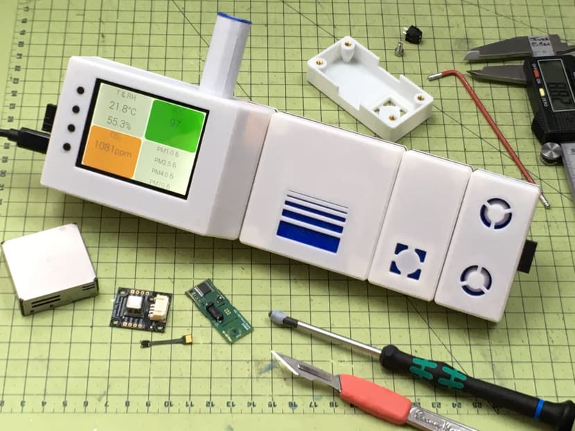
The DesignSpark Environmental Sensor Development Kit (ESDK) has Interchangeable Air Quality Sensors, which connect a bit like LEGO building blocks to a Raspberry Pi control unit, that sends your anonymised data to the cloud. It currently has 3 units as follows:
Particle Sensor - this is great for finding out if you have a dusty environment, which might be bad for allergies in the home, or perhaps safety in a workshop. It can even detect airborne particles from 3D Printing, or first-world problems like far-away BBQ smells, prompting you to get your washing in fast!
CO2 Sensor - this is an especially hot topic in 2020/21, as CO2 sensors have been used as a proxy for ‘good ventilation’ in the Pandemic. As yet we cannot detect a virus in air (too small, expensive, and too complex), but we can presume that if CO2 is building up in a school, cafe or office - that this is not good air, so open some windows.
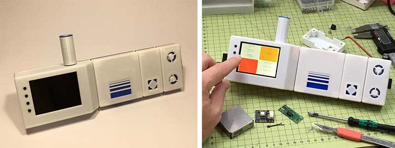
We also made a fun project - The Good Air Canary - (think Canary in the coal mine), as a desktop IoT device, which tells you when CO2 in your home office is getting too high. Studies show that most of us are adversely affected in terms of our lateral thinking and creativity if CO2 levels are above 4000ppm - a level which is reached in just 1 hour in a small office with the windows shut!
VOC, Temperature and Humidity Sensor - this ‘double’ sensor detects environmental basics or Temp and RH%, which helps calibrate the other sensors, but it also detects VOC index. This is a general ‘aggregated value of ‘nasty smells’ or Volatile Organic Compounds. So if you cut the cheese, this sensor will detect it. No more blaming the Dog.
GPS - Although this kit is designed to work Indoors, you could reasonably take it on a road trip, as so long as you protect it from rain and the elements, you might be interested to know what your walk to school or work is like, and likewise with safe driving - if the air is stuffy in the car, you probably are risking your life driving for hours with no ventilation. Indeed, some modern cars now incorporate forced air intake into AC units for this very reason.
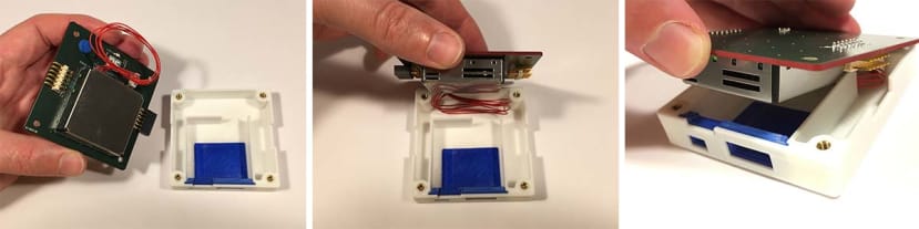
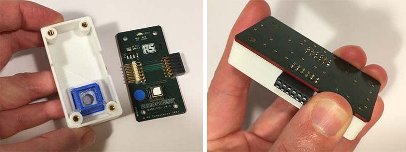
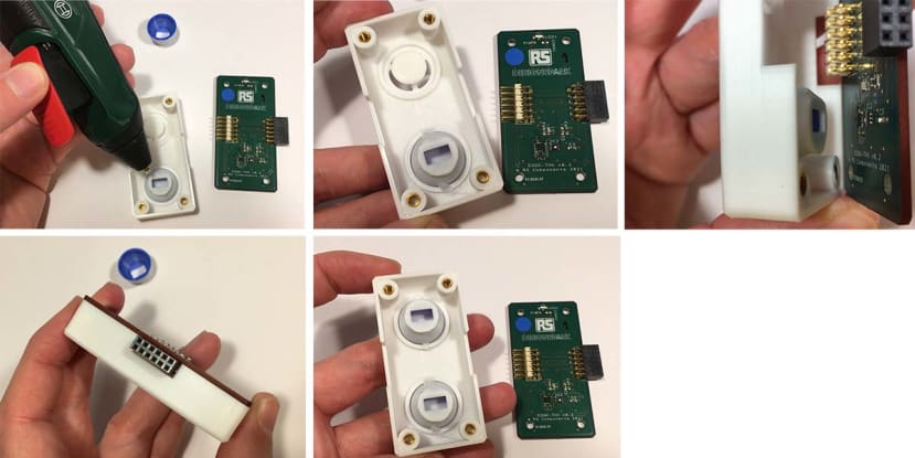
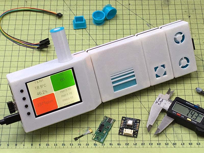
The Air Quality Kit, exploded to show how the enclosures fit together, and where each sensor is on the 'plug n play' circuit boards. The unit is powered by a Raspberry Pi 3B+, and has a 'Hat' with a touchscreen on it to control / view the air quality data.
Parts, Tools & Equipment.
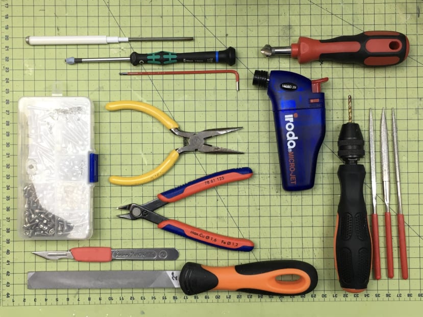
Mostly hand-tools will do, with only a few extras like Rotary Tool and Drill handy, but not essential.
Electronics:
- AQ PCB Set: 5 PCBs from DS/RS.
- 3B+ Raspberry Pi Recommended. Micro SD Card (32Gb or more).
- USB C Power Adaptor (for the Sensor Unit, not the RasPi).
- GPS Antenna & Cable (optional).
- Optional: Keyboard, Mouse, HDMI Cable for RasPi.
3D Printing:
- 3D Printer (or able to print files via a print provider like Protolabs).
- White Filament (+ 1 Alternative Colour, e.g. Blue, optional).
- Printer Nozzles of 0.6mm, though 0.4mm will also be fine.
Fixtures & Fittings:
- Brass Inserts. (027-8534)
- Hex M3 x 10mm Screws - 16x (028-1007)
- Hex M3 x 6mm Screws - 2x (or can saw-down larger to size) (028-0981) .
- Slotted Micro DIN Rail (046-7349)
Consumables:
- SuperGlue (1x3g tube will be ample).
- Sellotape.
- Sandpaper (suggested 400, 600, 1000 grit)
Tools:
- File (for metal, and plastic filing).
- Mini Blowtorch (or soldering iron) - to insert Brass Inserts.
- Hex 2.5mm Key / Driver (for Screws).
- Scalpel / Craft Knife.
- Calipers.
- Hot Melt Glue Gun.
Build guide
Section 1: Preparation Guide.
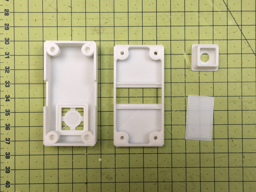
This guide will show you how to prepare the CO2 Sensor enclosure. This is essentially a ‘base’ and a ‘top’ unit, with an ‘insert’ for fitting close to the sensor on the PCB.
This process can be duplicated for each of the other units, with only minor variations. I have shown the Control Unit, as this is substantially different, but the same following hand-tool preparations are recommended to gain a nice finish post-printing.
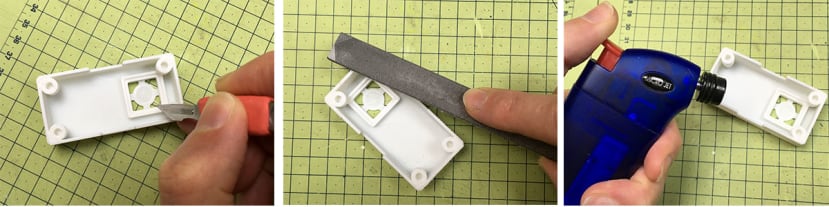
Use a scalpel to trim off any small defects, or strangs of filament.
Use a File (2nd Grade) to take off any large debris on the surfaces which will join together.
Use a mini blowtorch to singe away any wisps of filament.
You can also use fine sandpaper to finish edges if you wish also.
Top Tip: 3D Printer Variations.
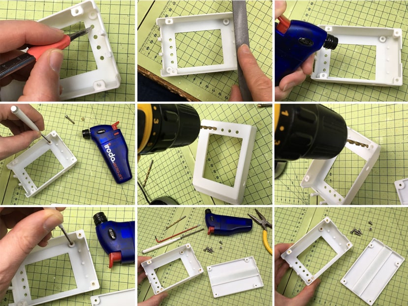
Depending on the setting of your 3D printer it is possible the holes for the Brass Inserts might need to be made slightly larger. Specifically 4mm diameter. Gently drill them out with a sharp drill bit, and the Insert should go in nicely. In case you are curious 'why not just print them the right size first of all?', this was a technique a learned at Dyson, and it turns out that making the holes of bosses slightly smaller means that when you drill them back, the quality of the plastic is better - and the grip is stronger. Also it takes out any variance between one 3D printer an another.
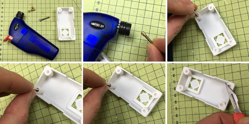
Insert the Threaded Brass Inserts by threading on onto a long bolt and then heading up with a blowtorch. Once slightly discoloured (or after 5 seconds, whichever is sooner), take the insert and press it into the hole of the boss. (If the fit is a bit tight - drill-out the hole with a 4.0mm drill bit).
Check the Insert is flush, and that the screw (and hence insert) is perpendicular to the surface. Unscrew the bolt to leave the Insert in place. Be aware the bolt may still be hot, so be careful.
Use a scalpel to trim off any excess plastic that may have been expelled when pressing in.
Tip Tip: Blowtorch vs Soldering Iron.
I strongly recommend using a mini blowtorch (or if not a cigarette lighter), as these are relatively inexpensive, and very useful in many electronics workshop activities. You can of course use a soldering iron, but there is a risk that if the tip protrudes through the other side of the Brass Insert too much - it may risk burning a small hole through your 3D printed case, so if you do use a soldering iron, select a 'chunky' tip that does not protrude. Lastly, if neither method appeals, you can use a hairdryer or heatgun to warm the Brass Insert, again, on a Bolt of adequate length to not get too hot to handle. Take care,
Do this for all 4 inserts.
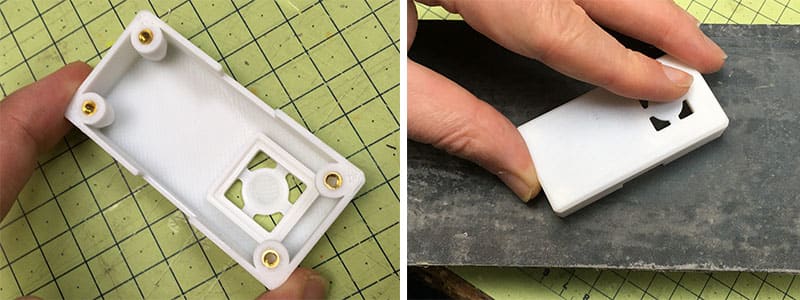
Use sandpaper to sand flush if you want it perfectly flat. Work from 400 to 600 to 1000 grit.
Be aware not to use water on wet and dry paper as this will stain the white PLA.
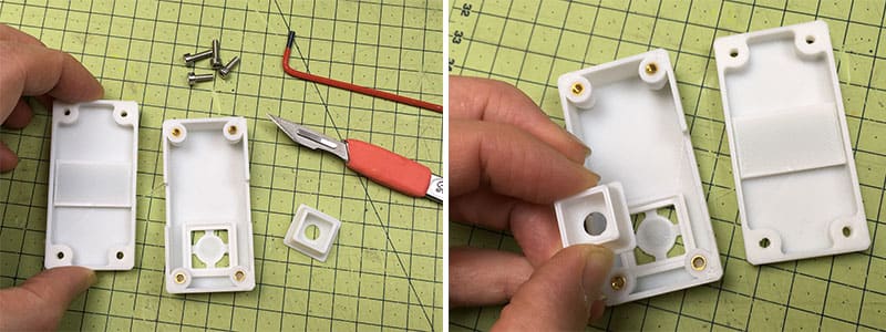
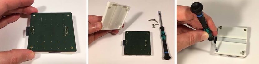
Take the Base piece and remove any support material or swarf from the holes - using a rotary tool and drill as shown. Use a scalpel to remove any burrs, and file if any stubborn remnants remain.
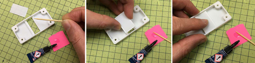
Use a sparing amount of Super Glue to stick down the ‘cover’ as shown. This is a precaution to ensure that no contact can be made between the PCB (and any oversize soldering, etc.) touching the metal DIN rail. Although unlikely this is not worth risking, and it also adds some strength to the unit as a whole. Ideally leave overnight to allow any off-gassing to subside, as this may interfere with the sensor readings.
Top Tip: If you are unsure about the Super Glue off-gassing I suggest using a less volatile glue, like Hot Melt, or even something that evaporates fast like Plastic Weld.
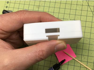
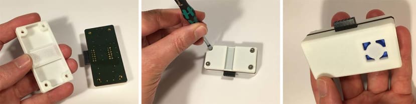
Your enclosures should now come together flush, as shown.
Now you have the parts ready for assembly with the PCBs. You can of course print all in one colour, or make the inserts coloured as I have done in the final models.
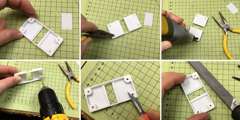
Do the same for the Control Unit.
These pictures show essentially the same process of ‘cleaning up’ the 3D Prints, and for the Control Unit, and the same intent is to ensure the Brass Inserts are flush and true, and that the two units come together cleanly with as few gaps as possible.
Top Tip: As shown, you may want to enlarge not only the Brass Insert Holes with a 4mm drill bit - but also the Button Holes, as shown. This will also correct for any tight fitting, from 3D printing / slicer variations.
You are now ready to assemble the enclosures with their corresponding PCBs.
Section 2: Assembly.
Part A: Control Unit.
Getting Started. This uses a Raspberry Pi 3B+. The PCBs shown here are green, as they were the final pre-production version, but yours will be an awesome DesignSpark-red colour!
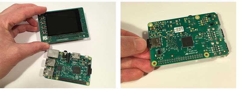
Check that you have removed the Screen Protector and that the Micro SD Card has been flashed with the Firmware/Software, and is inserted into the slot in the Raspberry Pi.
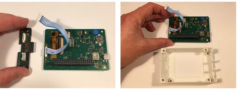
Check that the PMOD board connector fits, and connect it to the Screen/Hat, as shown. Set aside the PMOD (thin) board for later. Next, have the enclosure ready.
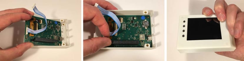
Slide the Hat into the enclosure as shown (it must be inserted at the ‘button side’ first. Take care that you allow the buttons to poke through the holes accordingly, before pressing the screen in all the way. Check the screen looks even, and the buttons are all through and ‘click’ when pressed.
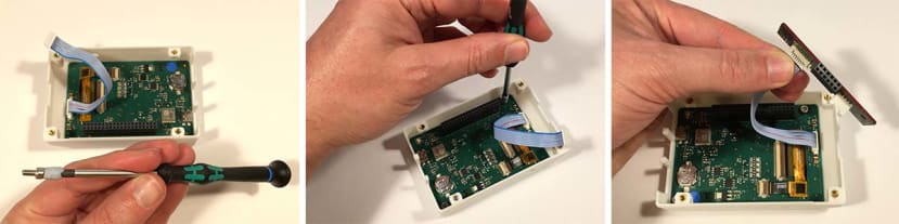
Screw in the Hat with 2x M3x6mm as shown in the last two images.
Tip - use Blutack to hold the screw on the tool, as shown. This helps for tricky operations, but also avoid making contact with any components and shorting out (the board may be unplugged, but the coin cell battery for example would not want to be shorted, so best to avoid any metal contact).
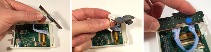
Now connect the PMOD Board to the cable as shown.
Optional: If you wish to add extra support for the screen, add a clip on the Support as shown. (This is only needed if you think people will be heavy-handed with the screen, which can flex a little if pressed aggressively). Lay in place as shown. (Do not screw in yet).

With no power supply connected: Take your Raspberry Pi and carefully push it onto the GPIO Header Pins as shown. Take care to ensure they align at either end, as failure would likely blow up the board. Press down with increasing pressure, taking care to keep the board level (ie don’t press on the opposite side as this will bend the pins). Keep pushing until fully docked, and the Raspberry Pi PCB will be level with the enclosure bosses, and should not wiggle around too much.
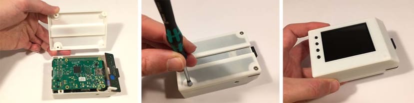
Take the baseplate, and screw in as shown with the M3x12mm screws. Use the ‘engineer’s tightening’ style - which is to tighten everything loosely, then go round again to firmly tighten the screws. It need only be ‘finger tight’ - so as not to overly clamp the PCBs. And there you have the main control unit done!
Do not power on yet, as you should ideally connect a sensor unit when using it for the first time.
Part B: Particle Sensor.
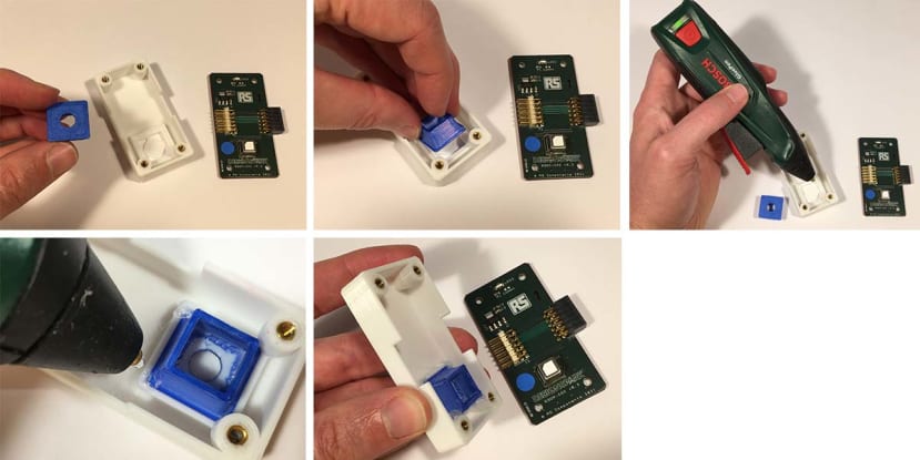
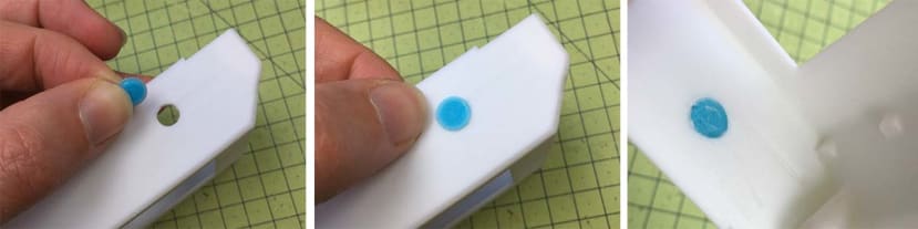
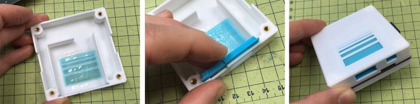
Assemble the parts for the Particle Sensor Unit as shown. Take the ‘coloured sheet’ and with some sellotape applied, stick it in place. If you wish to add a tiny dab of Hot Melt to hold it in place more securely, please do, but you may also wish to change the colours, so perhaps do this when you are certain with the colour scheme you fancy.
Likewise, press in the Insert as shown. The fit should be squirt snug, but if loose, you can also apply some Hot Melt to secure in place. Avoid Super Glue near the sensor inlets/outlets!
Taking care with the cables, to coil them as shown, in an even art (or yours may be shorter if this is an updated version!), use the ‘top area’ to stow the cables as shown in the second image, and then lower the PCB assembly, ensuring no cables are pinched/snagged/etc.
Place in alignment with the holes as shown. Screw down the Base Plate as shown.
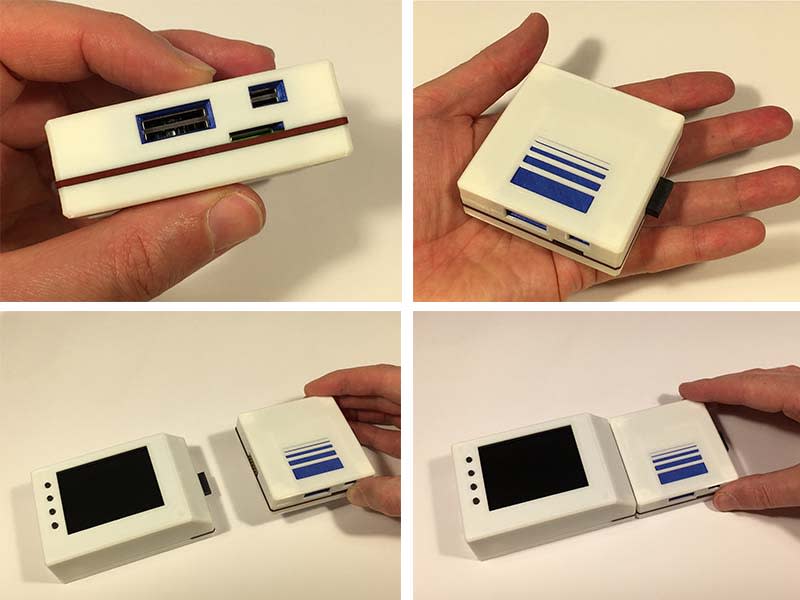
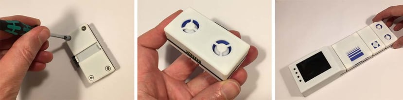
The assembly should fit flush as shown. You can show dock this with the Main Control Unit.
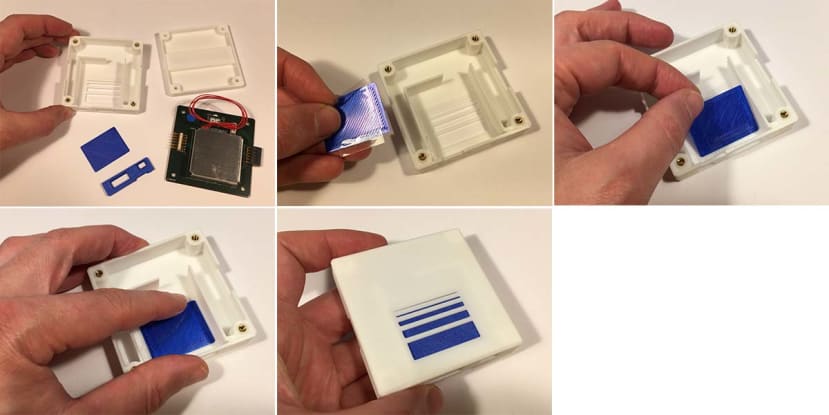
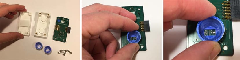
Part C: CO2 Sensor.
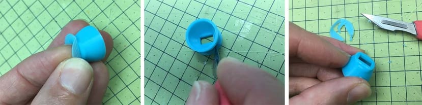
Assemble the components as shown. Test fit the Blue insert. If All is fitting snugly - apply some hotmelt glue to secure it into place. (Hot Melt is preferable to Superglue, as it has less off-gassing, and can be undone more easily. It also has some elasticity, which takes up any tolerance variance of the build in a favourable way. Just be sure to clear away any ‘strings’ of glue to avoid messing up the sensors.
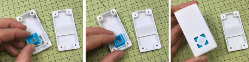
Whilst the Hot Melt is still pliable, test fit the assembly of the enclosure top onto the PCB, and check it fits without need to press hard, or that it is uneven.
Screw on the Base unit, and it should look as follows!
Part D: VOC + Temp + RH% Sensor.
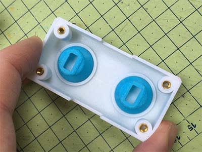
Assemble parts as shown. First of all check, the ‘Collar’ fits over the two sensors nicely. It should be snug, but not touching the edges. If you have any interference with any of the small components on the PCB, we recommend carefully trimming any excess of the 3D Printed Part so as it fits without any contact/collision.
Note: You may have realised that both the sensors are in the same single Collar, and yet there are two. You are correct that the ‘top’ inlet is purely cosmetic. Originally they were apart but later were placed side by side for better technical performance.
The purists along us will perhaps disapprove of this conceit, but speaking from the user perspective, having a more distinct looking unit (ie less like the CO2 Sensor) simply makes things easier to recognise, so we hope this is forgivable!
(If you simply cannot abide by this, it’s an easy edit in CAD to delete and ‘smooth over’ the top inlet).
As with the other sensors - apply a small dab of Hot Melt to the collar, and position such that you can check alignment with the sensors by looking in between, whilst closing together. If all is well, there should be no force required to press the PCB and enclosure top together. Add the second ‘dummy’ collar as shown.
Screw unit Base on with care. Do not overtighten.
Done!
Part E: Optional: GPS Setup.
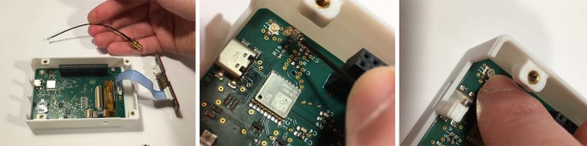
Take the Cable for the GPS as shown and press gently, but firmly onto the connector in the corner, as shown. Try to press on ‘squarely’ - no not ‘rock’ one side first. It should snap into place.
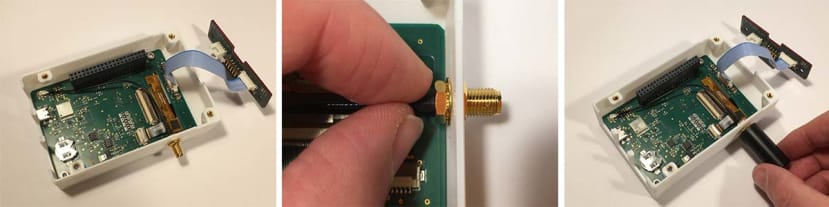
Pass the screw connector through the wall, and tighten the nuts on as shown. Lastly, screw on the GPS aerial as shown. (If you imagine removing the aerial often, we have included a ‘locking piece’ that fits on the inside to hold the screw in place, add this before you screw the nuts in place.
And you’re done! You can now add the ‘vanity cover’ onto the GPS Aerial, and safely power it up to test.
Note: If You do not want to have the GPS Aerial, you can either ‘fill over’ the hole in CAD, or insert the ‘tab’ as shown, and stick inside with some Hot Melt (better than SuperGlue as you can remove later if needed).
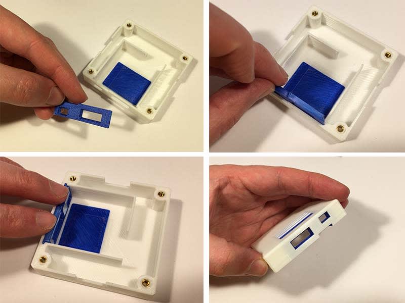
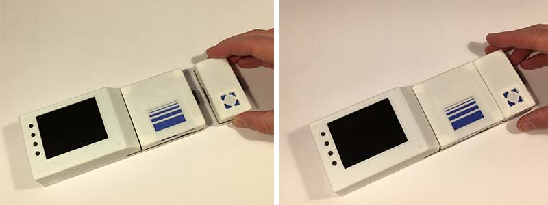
Part F: Changing Inserts (Colours and Tolerance).
The Coloured Inserts (shown above as Dark Blue, and below in Light Blue) are not just cosmetic: They were designed to allow you to print the enclosures in a relatively ‘coarse’ resolution (say a 0.6mm nozzle, with a ‘draft’ layer of 0.32mm height). Although you can certainly print the Inserts at the same resolution on your 3D Printer, it is advisable to at least put the 0.6mm layer height to ‘standard’ quality of 0.2mm, but if you can try to print with the smallest nozzle you have and the smallest corresponding layer height. This means the fit will be better.
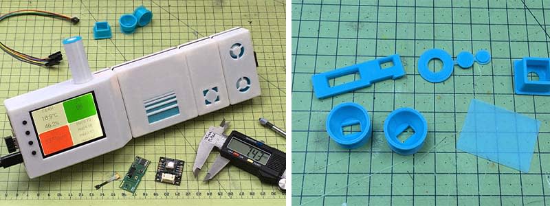
The second advantage of this is that should you have any issue with the fit of your interface between the Sensor/PCB and the Insert - you can adjust this without having to redesign and reprint the entire enclosure. This hopefully saves time, effort and money.
The ‘Cup’-shape of the VOC Sensor units has a ‘top hat’-style brim on it. This is so the piece does not fall over when printing (and yet does not require print support). This is only 0.5mm thick, so can be easily cut off with a scalpel or side cutters.
Now that you get the idea, the same can be done for the CO2 Inserts
And of course the Particle Unit
Part G: Adding DIN Rail (for structural support, and wall mounting).
Each of the Units has been designed to slide onto a DIN Rail. DIN Rails are a standardised section of metal, which various electronics are added. Chances are you have them in your home fusebox, or in a server centre at work. We have used ‘mini’ DIN Rail here, as it is universally available and can be cut to any length using a hacksaw or bandsaw.
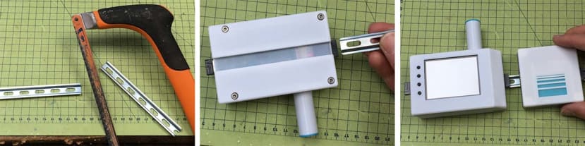
You may find it helpful to file off any burs from sawing. DIN Rail often comes in 1m lengths, and I would suggest you cut a few sections for the Control unit + 1, 2 and 3 of the Sensor Modules, so you have all variations ready for future use.
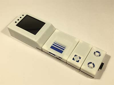
All done
We hope you’ll consider signing up to the AQ Beta Test Programme, and you could be one of 50 lucky participants to receive one of these kits - just tell us what you would do that would make good use of the air quality data you intend to collect. Are you trying to monitor forest fires, investigate pollutants from industrial factories, or even understand if your gas cooker is unsafe? We hope that you’ll join us on this journey of what we call Activist Engineering - putting state-of-the-art technology in the hands of technical people who want to make a difference.