Aluminum Electrolytic vs. Aluminum Polymer Capacitor and how its benefits are used properly
Follow article
 Dave from DesignSpark
How do you feel about this article? Help us to provide better content for you.
Dave from DesignSpark
Thank you! Your feedback has been received.
Dave from DesignSpark
There was a problem submitting your feedback, please try again later.
Dave from DesignSpark
What do you think of this article?
1. Understanding Polymer Electrolytic Capacitors
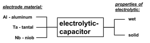
Aluminum polymer capacitor (also called polymer electrolytic capacitors or in short polymer e-caps) is a sub-form of the electrolytic capacitors. The special feature of these capacitor types is that a conductive polymer is used instead of a liquid electrolyte. This requires a special processing step, which is carried out during production. In this chemical reaction, the so-called polymerization, by heating, the still liquid monomer that has been impregnated in place of electrolyte in the separator paper is cross-linked to a solid polymer. This process is typically done at a temperature of about 100°C. Once completed, the polymer is solidified indefinitely. The various combinations that are possible today for electrolytic capacitors fabrication in terms of electrodes and the property of the electrolyte are shown in Fig. 1.
 |
|
Fig. 1: Construction possibilities of electrolytic capacitors |
Furthermore, there is the possibility of hybrid construction of electrolytic capacitors. This is a combination of wet electrolyte and solid polymer. Aluminum electrolytic and aluminium polymer capacitors have very good behaviour against bias effects of voltage and temperature. Furthermore, aluminium polymer capacitors have very good ageing characteristics. In comparison to ceramic capacitors, polymer electrolytic capacitors offer significant advantages, especially their DC bias performance. In addition, the use of polymer capacitors becomes interesting when increasing the capacitance while maintaining cost. The special design process can also be used to significantly reduce the parasitic effects (here especially the ESL). This means for applications the potential to handle high ripple current, have low parasitic inductances, high reliability and very good temperature properties. The equivalent circuit of a capacitor is shown in Fig. 2. It should be noted that polymer electrolytic capacitors have an increased leakage current compared to normal aluminium electrolytic capacitors and therefore are usually unsuitable for small handheld battery applications.
 |
|
Fig. 2: Equivalent circuit diagram of a real capacitor |
The high reliability is proven by the significantly longer lifetime of polymer electrolytic capacitors. However, when it comes to high vibration, the specific circumstances of the application should be considered, as aluminum polymer capacitors may not be the optimal choice here. This is due to the property of the solid polymer because it cannot absorb vibrations as well as a liquid electrolyte. However, it has to be considered that in terms of volume for a defined capacity and voltage, the normal electrolytic capacitor still has advantages. At Würth Elektronik eiSos, for aluminium polymer capacitors the capacitance values range from 10 μF to 2 mF with a voltage range from 6.3 V to 100 V in a wide variety of designs. Due to their excellent electrical properties, the possibilities of using polymer electrolytic capacitors are very diverse, ranging from traditional backup solutions of voltages, buffering supply voltages from ICs, bypass or decoupling of signals, filter applications to voltage smoothing of switching regulator applications. This white paper discusses the use of aluminum polymer capacitors in the field of filtering and voltage smoothing.
2. The Buck Converter - General Setup
To demonstrate the positive effects of the polymer electrolytic capacitor a buck converter is used. The input voltage is 12 V and the output voltage has been set to 5 V. The load is a pure ohm load of 5 Ω. This results to a current of 1 A flowing through the resistor. This setup serves as a basis to make the performance of polymer electrolytic capacitors clear. The design is used for both EMC measurement and voltage ripple output measurements with always the same load. From the EMC point of view, a buck converter is much more critical at the input side. This is due to the discontinuous current consumption based on the fast switching processes of the semiconductors. As a result of this topology, there is already an "LC filter" at the output, which integrates the discontinuous current on the high side (refer to Fig. 3).
 |
|
Fig. 3: Principle of a buck converter |
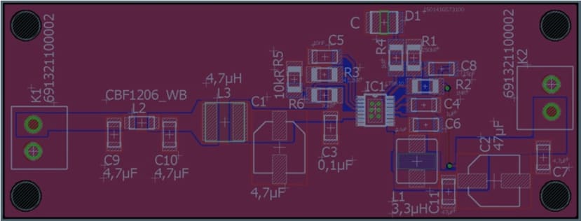
The construction and design of the buck converter were based on the specifications of the datasheet and designed with the default values for the coil and capacitors. The inductance values of the coil and the capacitance of the input and output capacitors were verified by the manufacturer's data sheet and with their simulation software. This was especially important when using only one aluminium electrolytic capacitor. Due to the very high ESR value, the stability of the regulator was impaired. To counteract this effect, a capacitor was additionally attached to the feedback loop. This additional capacity ensures stability even at high ESR values. In Fig. 4 the circuit diagram of the buck converter and in Fig. 5 the associated layout is shown.
 |
|
Fig. 4: Schematic of the buck converter |
The layout consists of two layers, each with full copper areas on the top and bottom sides with connection to ground. The layout itself could still be improved at various points. Above all, the connection of the components to the ground layer still needs optimization to achieve a better filtering effect. It can clearly be seen in the measurement of the output capacitor that the high parasitic inductance causes voltage peaks on the output signal.
 |
|
Fig. 5: Layout of the buck converter |
3. The EMC measurement
The measurements were made according to the CISPR 32 standard (which replaces CISPR 22 and 15) in an RF-shielded chamber with the corresponding connection to the ground surface of the cabin, see Fig. 6. The test receiver was an R&S ESRP 3 and as network simulation an ENV216 two-wire V-net simulation was available. During the measurement, in the first step, further input filters on the layout were dispensed; only in the last measurement was a T-filter with a separated coil placed. This filter was constructed according to the specifications in the datasheet.
 |
|
Fig. 6: Setup of the EMC measurement according to CISPR 35 |
For the first measurement, an aluminium electrolytic capacitor WCAP-ASLL 865060343004 was used for the input capacitor C1 (REDEXPERT: http://we-online.com/re/46R2lMfx). The electrical properties of the capacitor are as follows: Capacitance 47 μF, rated voltage 16 V with an ESR 411 mΩ and ESL 19 nH. The associated measurement result is shown in Fig. 7.
 |
|
Fig. 7: First EMC measurement with an aluminium electrolytic capacitor as C1 |
It can be seen that the limit values of CISPR 32 class B are clearly exceeded. There are noise levels of up to 100 dBμV detectable. But where do these interfering signals come from? The capacitor as a real component has parasitic effects, particularly the ESR together with the parasitic effects of the layout (the lead inductance) generate a high-frequency voltage drop that can be detected by measurement. This is shown schematically in Fig. 8.
 |
|
Fig. 8: Schematic representation of the cause of the disturbances |
As a first approach to achieve acceptable levels of emissions and stay below the limits, an aluminium polymer capacitor can be used. The electrical properties in terms of capacity and rated voltage of the aluminium polymer capacitor are the same as those of the aluminium electrolytic capacitor. The design is also equivalent to the capacitance value of 47 μF and the capacitor fits the original landing pattern. The aluminium polymer capacitor used was a WCAP-PSLP 875105344006 (REDEXPERT: http://we-online.com/re/48TxCoJe) with a capacitance of 47 μF, rated voltage of 16 V and with an ESR 20.7 mΩ and ESL 3.9 nH. Due to the very low ESR and ESL, the following measurement of the interference spectrum is achieved, which can be seen in Fig. 9.
|
|
|
Fig. 9: EMC measurement with an aluminium polymer capacitor as the input capacitor |

It can clearly be seen that by changing only one component, the EMC performance was significantly improved. The voltage drop which is generated by the fundamental frequency and the first harmonic of this frequency is reduced and thus less interference is generated. However, the limit could not be met and therefore further filters have to be placed. The structure of the input filter was based on the information in the datasheet. Therefore, the filter has the following insertion loss (in a 50 Ω system), as shown in Fig. 10.
 |
|
Fig. 10: Built-in input filter with shown filter performance |
The input filter was then included on the PCB and another measurement performed. The result is shown in Fig. 11 where the interaction between the aluminium polymer capacitor and the input filter is visible.
|
|
|
Fig. 11: EMC measurement with input filter and aluminium polymer capacitor |

The combination of input filter and low ESR and low ESL polymer electrolytic capacitance makes it possible to push the level broadband below the limit of class B. Values of less than 40 dBμV (Average & Quasi-Peak) are easily possible (compared to the first measurement with around 100 dBμV) and so, the measurement is passed.
4. Comparison of the ripple of the output signal
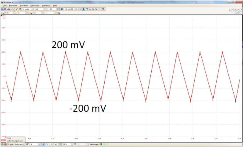
For the output capacitor of a buck converter, a certain capacitance is required in order to keep the control loop stable and hence the output voltage stable. If the output voltage reduces the capacitance value, the worst-case scenario is the converter can no longer meet its specification (for example during load changes). This must be taken into account, especially when operating with class 2 ceramic capacitor (e.g. X7R and X5R). In the following chapter, the effect of the resulting ripple on the output signal will be considered. The first measurement in Fig. 12 shows the result of the output ripple of the switching regulator when only one aluminium electrolytic capacitor is used. The capacitor used is a WCAP-ASLL 865060343004, the same as used previously (REDEXPERT: http://we-online.com/re/46R2lMfx). The electrical properties of the capacitor are as follows: Capacitance 47 μF, rated voltage 16 V with an ESR 411 mΩ and ESL 19 nH. The high ESR value results in a peak-to-peak value of 400 mV. At least, this means a voltage ripple of 8% at an output voltage of 5 V.
|
|
|
Fig. 12: Residual ripple at the output of the buck converter if only one aluminium electrolytic capacitor is used |
Even with two aluminium electrolytic capacitors of the same type in parallel, the resulting ESR is still 205.5mΩ and thus clearly too high. Another aspect that should not be neglected is the ripple current through the capacitor. This leads to heating of the component and leads to the failure of the capacitor. Therefore, the ripple current capability of aluminium electrolytic capacitors must always be checked. In the case of polymer electrolytic capacitors, due to the low ESR, the heating of the component at the same ripple current is significantly lower and, in comparison, therefore significantly larger ripple currents are capable without thermally overloading the component. A comparison of the ESR of the aluminium electrolytic capacitor and the ESR of the polymer electrolytic capacitor is as shown in Fig. 13. The measurement of the residual ripple of the output signal with the polymer capacitor as an output capacitor is shown in Fig. 14. The aluminium polymer capacitor used was a WCAP-PSLP 875105344006 (REDEXPERT: http://we-online.com/re/48TxCoJe) with a capacitance of 47 μF, rated voltage of 16 V and with an ESR 20.7 mΩ and ESL 3.9 nH.
 |
|
Fig. 13: Comparison of the ESR of the aluminium and aluminium polymer capacitor |
|
|
|
Fig. 14: Measurement of residual ripple when using the aluminium polymer capacitor at the output |

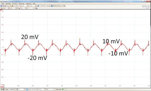
The peak-to-peak value of the measurement is now only 50 mV and therefore within an acceptable range. The voltage peaks as seen in Fig. 14 are caused by parasitic inductance during the switching. Since no one would use single aluminium polymer electrolytes alone in a real application; it is advisable to place an MLCC in parallel to the aluminium polymer capacitor. Thus, the parasitic effects can be minimized and a very clean output signal is achieved, as shown in Fig. 15. The MLCC used was a X7R ceramic with a capacitance of 4.7 μF and rated voltage of 16 V (REDEXPERT: http://we-online.com/re/46R0ibYPluS). If the layout of the PCB will be optimized, too, a peak-to-peak value of 20 mV is expected, see also Fig. 15.
|
|
|
Fig. 15: Measurement of residual ripple using an aluminium polymer capacitor and an MLCC |
5. Lifetime consideration
The lifetime of electrolytic capacitors is very important in industrial applications and other application where a high lifetime is required. Here, the capacitor is not used as a kind of predetermined breaking point (also called planned obsolescence) as it is in consumer electronics but is as a durable and reliable component. The life of a capacitor depends on many factors of the application. An important factor is the temperature or rather thermal load, as it is responsible for the fact that internal structures age over time and the electrical properties deteriorate. This results in increased leakage current, increasing the ESR, which in turn leads to a further increase of the temperature. The reason for the temperature increase is the power loss generated by the ESR. If these limits are not exceeded, high lifetime expectancies are possible when the inner temperature load of the component is in a lower range. A comparison of the lifetime of aluminum electrolytic and aluminum polymer capacitors by temperature load is listed here. The bases of this consideration are two formulas. With liquid electrolytic capacitors, the expected lifetime doubles when the temperature at the component is reduced by 10°C (2). For polymer electrolytic capacitors, the life increases tenfold when the temperature at the component is reduced by 20°C (1).
|
Formula for aluminum polymer capacitors:
Formula for aluminium electrolytic capacitors: |


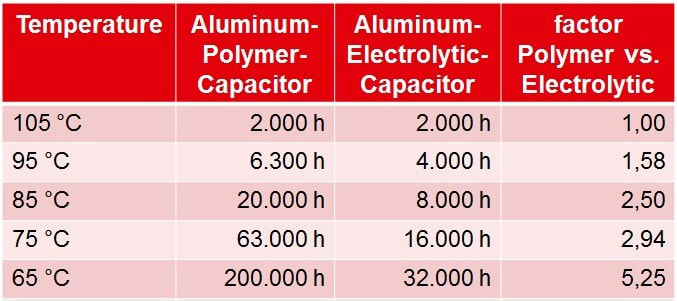
To further illustrate this, the calculated lifetime values are shown in Table 1 for some example temperature values. Here, the maximum specified component temperature is used to compare aluminum electrolytic and aluminum polymer capacitors.
 |
|
Table 1: Lifetime overview of different ambient temperatures |
The table is divided into four columns. The application temperature is defined in the formulas (1) and (2) as the ambient temperature Ta. The hour’s definition at 105°C in the two following columns for the aluminium polymer and aluminium electrolytic capacitor is the nominal lifetime of the component Lnom. This is linked to the maximum specified temperature at the component and is defined as T0. The other hours in the table are the calculated lifetimes Lx using the formulas (1) and (2). The calculated factor in the last column is the relation between the calculated lifetime for aluminium electrolytic and aluminium polymer capacitors. In the aluminium polymer capacitor column, the calculated lifetime is 200,000 h at 65°C ambient temperature. This means a theoretical lifetime of 22 years. To guarantee such a lifetime is not possible. The typical maximum guaranteed lifetime varies for different vendor and is between 13 and 15 years.
Furthermore, you can clearly see in this table at which ambient temperature aluminium polymer capacitors have their advantage in lifetime. If the specified component temperature for aluminium electrolytic and aluminium polymer capacitors is the same (for example 2000 h at 105°C), it can be seen at 95°C the polymer electrolytic capacitor has a longer lifetime. Only in cases of aluminium electrolytic capacitors with a long specified lifetime at the maximum specified component temperature (for example 5000 h at 105°C) has a higher intersection point but the point of intersection will always occur (see Fig. 16). The specified hours in this diagram are always the nominal lifetime value of the component at this temperature. Apart from this advantage, of course, the other parameters of the capacitors must be compared. It may be that in a special application the expected lifetime is the same, but the better ESR and ESL are critical to the application and speaks for the aluminium polymer capacitor.
 |
|
Fig. 16: Overview of the expected lifetime of aluminium and aluminium polymer capacitors |
6. Summary
Aluminum polymer capacitors, because of their construction, have significant advantages for electronic applications. Low ESR and low ESL values in addition to very high expected lifetime make this technology extremely interesting for many diverse applications. Therefore, the possible use should be considered based on the information provided in this White Paper. This can improve the behaviour of the design and ultimately increase the performance of the application.
Find this article as pdf below!
IMPORTANT NOTICE
The Application Note is based on our knowledge and experience of typical requirements concerning these areas. It serves as general guidance and should not be construed as a commitment for the suitability for customer applications by Würth Elektronik eiSos GmbH & Co. KG. The information in the Application Note is subject to change without notice. This document and parts thereof must not be reproduced or copied without written permission, and contents thereof must not be imparted to a third party nor be used for any unauthorized purpose.
Würth Elektronik eiSos GmbH & Co. KG and its subsidiaries and affiliates (WE) are not liable for application assistance of any kind. Customers may use WE’s assistance and product recommendations for their applications and design. The responsibility for the applicability and use of WE Products in a particular customer design is always solely within the authority of the customer. Due to this fact it is up to the customer to evaluate and investigate, where appropriate, and decide whether the device with the specific product characteristics described in the product specification is valid and suitable for the respective customer application or not.
The technical specifications are stated in the current datasheet of the products. Therefore the customers shall use the data sheets and are cautioned to verify that data sheets are current. The current data sheets can be downloaded at www.we-online.com. Customers shall strictly observe any product-specific notes, cautions and warnings. WE reserve the right to make corrections, modifications, enhancements, improvements, and other changes to its products and services.
WE DO NOT WARRANT OR REPRESENT THAT ANY LICENSE, EITHER EXPRESS OR IMPLIED, IS GRANTED UNDER ANY PATENT RIGHT, COPYRIGHT, MASK WORK RIGHT, OR OTHER INTELLECTUAL PROPERTY RIGHT RELATING TO ANY COMBINATION, MACHINE, OR PROCESS IN WHICH WE PRODUCTS OR SERVICES ARE USED. INFORMATION PUBLISHED BY WE REGARDING THIRD-PARTY PRODUCTS OR SERVICES DOES NOT CONSTITUTE A LICENSE FROM WE TO USE SUCH PRODUCTS OR SERVICES OR A WARRANTY OR ENDORSEMENT THEREOF.
WE products are not authorized for use in safety-critical applications, or where a failure of the product is reasonably expected to cause severe personal injury or death. Moreover, WE products are neither designed nor intended for use in areas such as military, aerospace, aviation, nuclear control, submarine, transportation (automotive control, train control, ship control), transportation signal, disaster prevention, medical, public information network etc. Customers shall inform WE about the intent of such usage before design-in stage. In certain customer applications requiring a very high level of safety and in which the malfunction or failure of an electronic component could endanger human life or health, customers must ensure that they have all necessary expertise in the safety and regulatory ramifications of their applications. Customers acknowledge and agree that they are solely responsible for all legal, regulatory and safety-related requirements concerning their products and any use of WE products in such safety-critical applications, notwithstanding any applications-related information or support that may be provided by WE. CUSTOMERS SHALL INDEMNIFY WE AGAINST ANY DAMAGES ARISING OUT OF THE USE OF WE PRODUCTS IN SUCH SAFETY-CRITICAL APPLICATIONS.
USEFUL LINKS
Application Notes:
http://www.we-online.com/app-notes
REDEXPERT Design Tool:
http://www.we-online.com/redexpert
Toolbox:
http://www.we-online.com/toolbox
Product Catalog:
http://katalog.we-online.de/en/
CONTACT INFORMATION
Würth Elektronik eiSos GmbH & Co. KG
Max-Eyth-Str. 1, 74638 Waldenburg, Germany
Tel.: +49 (0) 7942 / 945 – 0
Email: appnotes@we-online.de