A Custom USB Power Supply for a Military Surplus Land Rover
Follow article
 Dave from DesignSpark
How do you feel about this article? Help us to provide better content for you.
Dave from DesignSpark
Thank you! Your feedback has been received.
Dave from DesignSpark
There was a problem submitting your feedback, please try again later.
Dave from DesignSpark
What do you think of this article?
Building a custom USB power supply for use with 24V vehicle electrics.
Many military vehicles use 24V electrics rather than 12V, since a higher voltage supply is usually required for operating radio equipment. Some vehicles do mix the two and have 12V standard electrics for the engine and lights, with a separate 24V circuit for radio equipment. However, as one might expect, this has proved problematic at times and the British Army at least eventually decided to standardise on 24V electrics across its fleet.
While there are plenty of 12V input USB adapters, those rated for 24V appear to be much thinner on the ground and none could be found which were guaranteed to be good for at least 28V input. Hence with this in mind and the slightly unusual input connector, plus a requirement for a more user-friendly secondary output connector for daisy chaining, a custom solution seemed in order.
In this article, we’ll take a look at constructing a simple adapter to enable USB-powered devices to be used with vehicles that have 24V nominal electrics and in this case, an ex-army Land Rover.
Land Rover Wolf
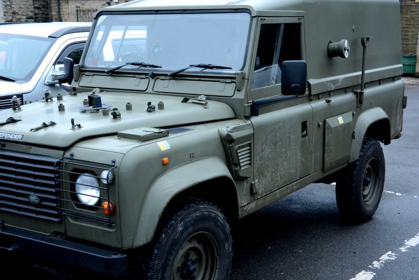
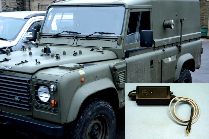
The vehicle in question is a Land Rover Defender eXtra Duty (XD), to use its manufacturer name, or Truck Utility Medium (TUM) High Specification (HS), it's British Army designation. More commonly though it is simply referred to as a Land Rover Wolf and is essentially an uprated version of the much-loved commercial Land Rover Defender.
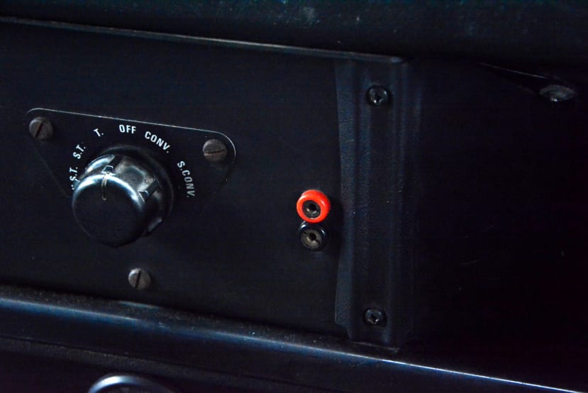
A 2-pin Lucas auxiliary power socket fitted to the dash has been a common feature of military Land Rovers across the decades and this is typically used with a simple inspection lamp.
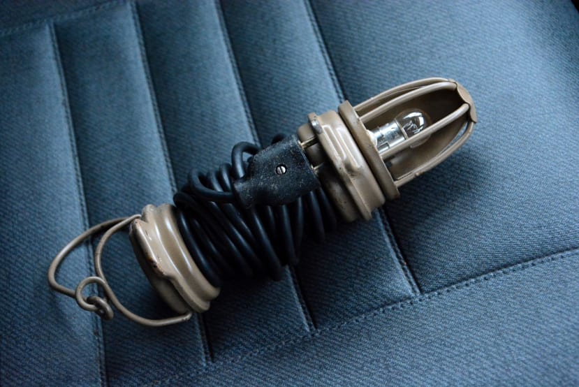
However, this will also provide a convenient power source for our USB power supply.
Requirements
The requirements were quite simple and as follows:
- 2x USB charging sockets providing up to 3A total
- An additional output carrying both 5V and 24V
- Fused input
- Power indicator
The additional output is so that other devices can be powered if so desired, which may use a 5V or 24V supply. The fuse is an obvious safety measure and indicator so we know if there is a problem.
Components
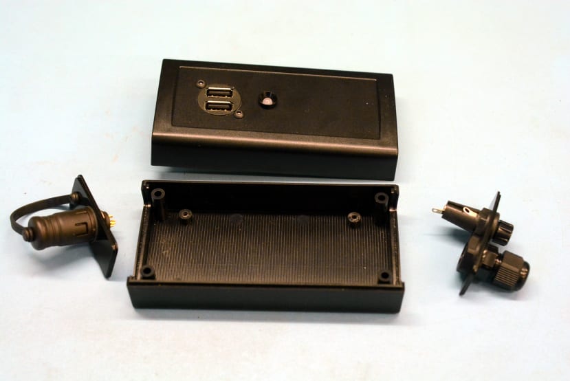
An RS Pro ABS enclosure was selected from a design with many different sizes available. In addition to top and bottom halves, this design features removable end panels, which makes it easier to mark them out and drill for cable entry, fuse holder and an output connector.
The bill of materials is as follows:
- RS PRO Black ABS Enclosure (192-0806)
- RS PRO Black Nylon Cable Gland, M12 (669-4654)
- RS PRO Control Cable, 2 Cores, 0.5 mm², YY, Unscreened (827-4234)
- Bulgin 6.3A Panel Mount Fuse Holder for 5 x 20mm Fuse (359-5961)
- RS PRO 2A F Glass Cartridge Fuse, 5 x 20mm (056-3431)
- Single-Sided Stripboard FR-2 (100-4328)
- Vishay Bridge Rectifier, 3A, 100V, 4-Pin (700-5478)
- TRACOPOWER THD 15N DC-DC Converter (706-5701)
- RS PRO Straight, Panel Mount, Socket Type A 2.0 USB Connector (830-0074)
- RS PRO Green, Red, Yellow Panel Mount Indicator (020-6148)
- binder 720 Panel Mount Connector, 3 Contacts (046-9024)
- binder 720 Female Dust Cap IP67 Rated (734-5763)
- Lucas CAB185 2-pin auxiliary power plug
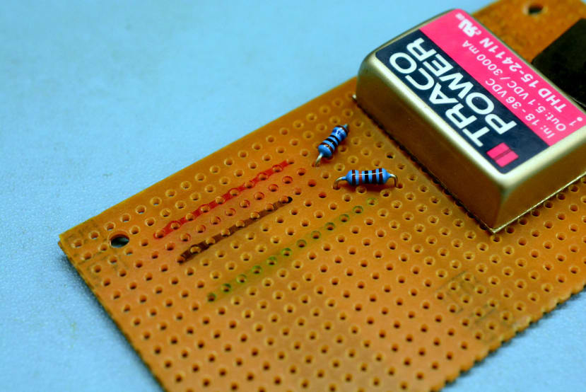
A Tracopower 15W DC-DC converter was selected with an input voltage range of 18-36V — bearing in mind that when the engine is running the supply will be somewhat higher at around 28V — and an output of 5.1V, which should provide our required up to 3A charging capacity.
Since the Lucas 2-pin connector is not polarised and so as to avoid potential damage, a bridge rectifier will be connected between the input and the DC-DC converter, meaning that it doesn’t matter which way the plug is inserted into the dash socket.
Assembly
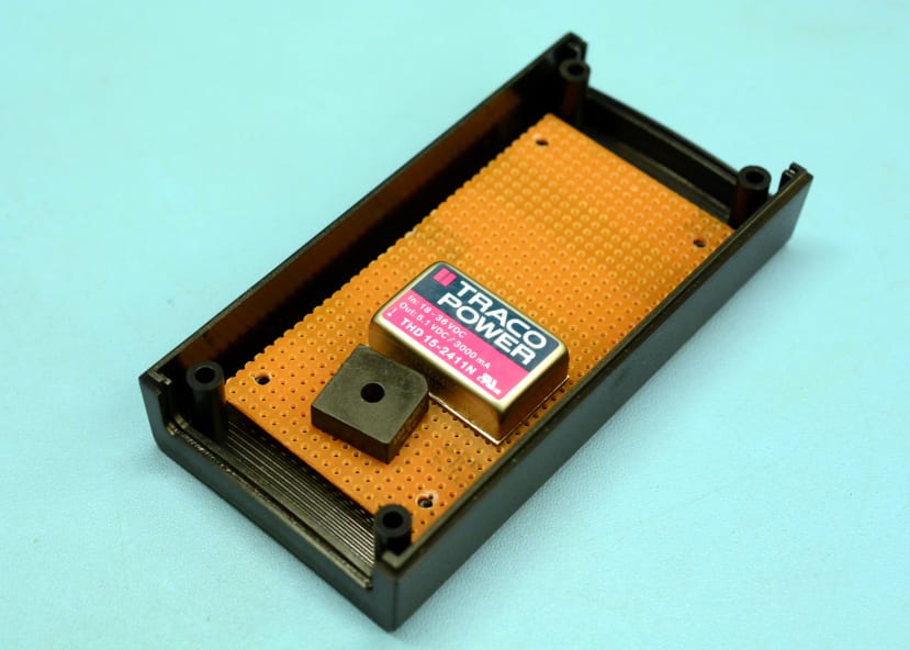
A piece of perfboard was cut to size and drilled so that it could be secured to the bottom half of the enclosure, as can be seen above, with the bridge rectifier and DC-DC converter also soldered.
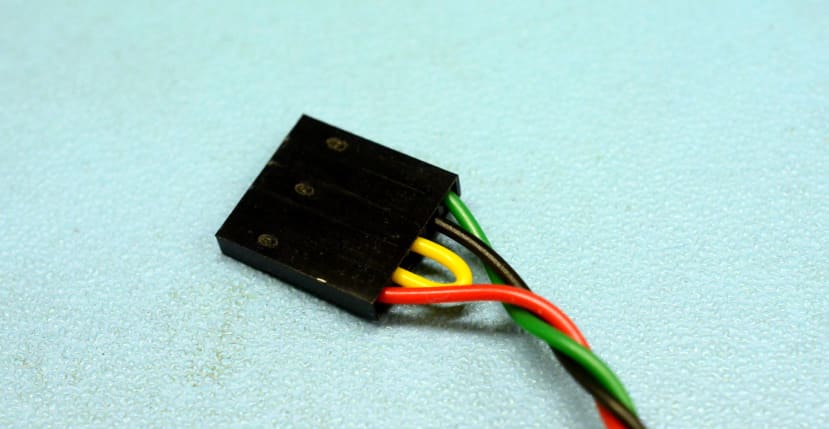
Box header cables were assembled to connect the USB socket to the perfboard. However, this was done before checking the space between the two and it turned out that it wouldn’t be possible to use these without a somewhat taller enclosure.
A great advertisement for measure twice and cut once!
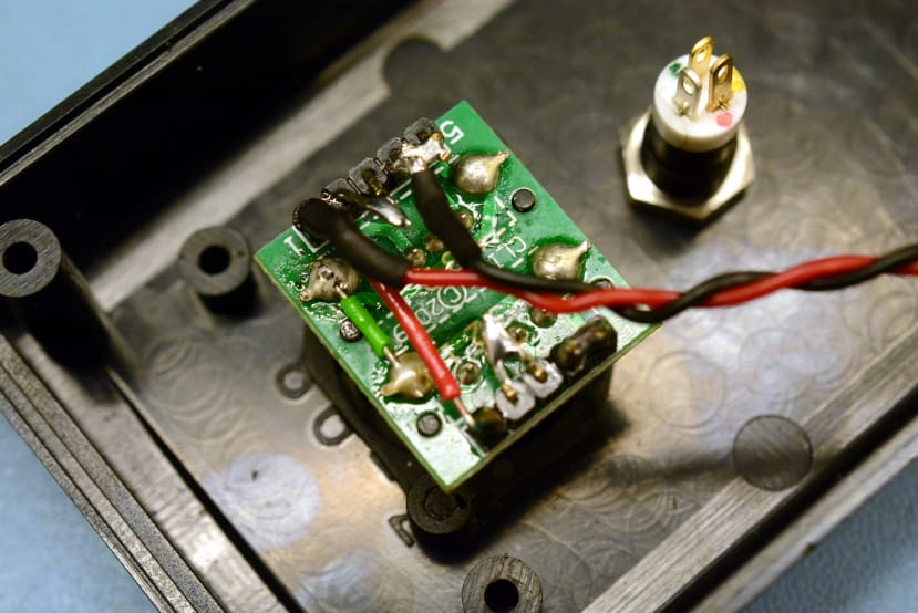
So instead cables were soldered directly to the USB connector pins. Which is nowhere near as neat, but at least functional.
USB Vcc and ground lines on each port were connected to each other and to the DC-DC converter output. The USB housing pins were also connected to ground; there appear to be differing views on this and best practice, with various considerations and some connecting housing to ground via an RC filter or a ferrite, for example — but here at least direct connection seemed appropriate.
The USB standard states that a dedicated charging port (DCP) without data must have a resistance of no greater than 200R between the data lines, so as to as signal its type. With this in mind, the data lines were simply shorted together on each port.
An indicator was fitted in the front panel next to the USB ports for power status. This features red and green LEDs and produces a third colour, yellow, if both are provided with power. The indicator is connected as follows:
- Green LED via 1K3 resistor to 24V input.
- Red LED via 160R resistor to 5.1V DC-DC converter output.
Hence in normal operation, this illuminates yellow and if illuminated green, this means that the vehicle is providing power, but there is no output. A lack of output could mean that the DC-DC converter has failed, but equally, it could also mean that something attached to the output is dragging the rail down and therefore signal that it should be disconnected.
The indicator illuminating red would be a rather strange situation since it would suggest an output without power input! Although it is possible that this might be seen in the rare event that equipment is providing power out in the backwards direction.
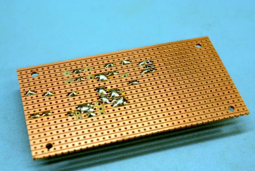
Above can be seen the perfboard underside, with cut tracks. Sadly, as is often the case, not long after one cut was made it was realised that with a slightly different strategy, the single black wire jumper on the opposite side wouldn’t have been needed and all solder bridges could have been used instead. The net result is oviously the same, but strategies to avoid use of wire jumpers can become something of a game with perfboard!
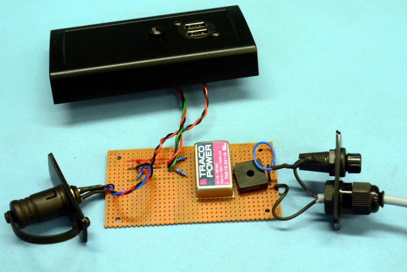
Hook-up wires were soldered in place next, ready for final assembly.
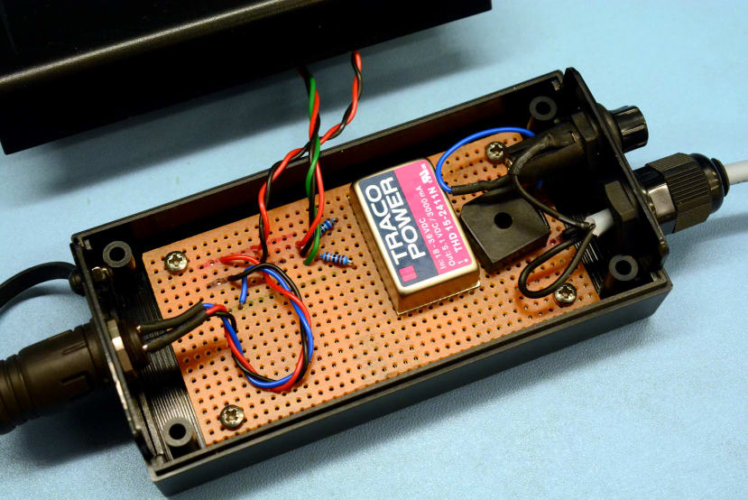
Then the perfboard was secure into the enclosure's bottom half.
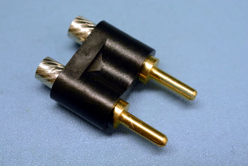
The 2-pin Lucas design plugs that are widely available at present are not of a particularly satisfying design when it comes to cable termination; wire is stripped and inserted into unscrewed hollow silver terminals, which are then screwed into the main body, crushing the wire.
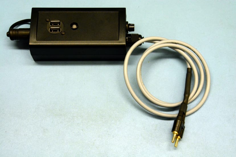
In any case, various pieces of heat shrink of different sizes were used to create something akin to strain relief and to provide some insulation on the connector back.
In use
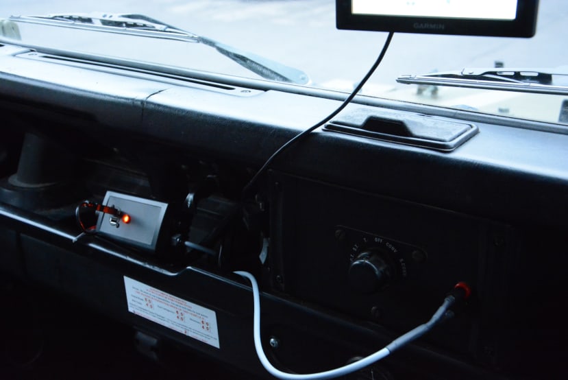
Above can be seen the custom PSU to the left-hand side, plugged into the 24V auxiliary power socket just to the right of the rotary light switch, with a satnav plugged into the power supply. Which finally means an end to having to remember to charge a USB power bank!