Compass Hat
Follow project
 Dave from DesignSpark
How do you feel about this article? Help us to provide better content for you.
Dave from DesignSpark
Thank you! Your feedback has been received.
Dave from DesignSpark
There was a problem submitting your feedback, please try again later.
Dave from DesignSpark
What do you think of this article?
 In The Engineering Edge Podcast episode "The everyday tech giving humans a sixth sense" I learnt about the Navibelt - a compass belt that assists blind people. I wanted to try and make something similar for myself ...
Parts list
| Qty | Product | Part number | |
|---|---|---|---|
| 1 | Adafruit Haptic Motor Controller Board | 124-5480 | |
| 1 | Seeed Studio 316040001 Mini Vibration Motor for Multipurpose | 184-5122 | |
| 1 | Slide switch,SP on-off-on PC thru-hole | 734-7334 | |
| 1 | ADAFRUIT Circuit Playground Classic MCU Development Board 3000 | 124-5504 | |
| 1 | ADAFRUIT INDUSTRIES 1059 GPS Module | 905-4637 | |
In The Engineering Edge Podcast episode "The everyday tech giving humans a sixth sense" I learnt about the Navibelt - a compass belt that has been developed into a high-quality navigation solution that assists blind people. I wanted to try and make something similar for myself ...
Note 1: This build was based on the Adafruit Tutorial https://learn.adafruit.com/circuit-playground-express-compass
Note 2: I was using a Circuit Playground Classic, rather than the Express, which is used in the Adafruit tutorial.
1) Set up the Arduino IDE and Circuit Playground, including the libraries, as described in the Adafruit Tutorial: https://learn.adafruit.com/introducing-circuit-playground/set-up-test-arduino
2) Position the LSM303 in the centre of the Circuit Playground with the boards back to back, and the X-axis running between the USB and power connections. Hot glue the LSM303 to the Circuit Playground.
3) Once the glue cools, wire the boards together. As we are using I2C the connections are:
- 3V to 3V
- GND to GND
- SDA to SDA
- SCL to SCL
In the photo below, the small round board is the LSM303. The x-direction is pointing to the right of the photo, the y-direction almost straight to the top of the picture.
I used red for the 3V power, black for ground, pink for SDA and orange for SCL.

In the bonus episode, I mention my wire strippers - this is them: RS Part Number (066-3617)

3) Before connecting the DRV2605L haptic motor board, program the Circuit Playground using the adafruit libraries, and calibrate the compass, as explained in the tutorial: https://learn.adafruit.com/circuit-playground-express-compass/arduino
This is the Adafruit code from the compass tutorial:
/* The Engineering Edge Compass Hat Project. Based on the code for the Circuit Playground Express compass (licence below), with adaptations by Andy Stanford-Clark and Lucy Rogers. Lucy is responsible for any errors.
/* Circuit Playground Express compass. */
/* Adafruit invests time and resources providing this open source code. */
/* Please support Adafruit and open source hardware by purchasing */
/* products from Adafruit! */
/* Written by Dave Astels for Adafruit Industries */
/* Copyright (c) 2018 Adafruit Industries */
/* Licensed under the MIT license. */
/* All text above must be included in any redistribution. */
#include <Wire.h>
#include <Adafruit_NeoPixel.h>
#include <Adafruit_Sensor.h>
#include <Adafruit_LSM303_U.h>
#include <math.h>
/* Assign a unique ID to this sensor at the same time */
Adafruit_LSM303_Mag_Unified mag = Adafruit_LSM303_Mag_Unified(12345);
// Replace these two lines with the results of calibration
//---------------------------------------------------------------------------
float raw_mins[2] = {1000.0, 1000.0};
float raw_maxes[2] = {-1000.0, -1000.0};
//---------------------------------------------------------------------------
float mins[2];
float maxes[2];
float corrections[2] = {0.0, 0.0};
// Support both classic and express
#ifdef __AVR__
#define NEOPIXEL_PIN 17
#else
#define NEOPIXEL_PIN 8
#endif
// When we setup the NeoPixel library, we tell it how many pixels, and which pin to use to send signals.
// Note that for older NeoPixel strips you might need to change the third parameter--see the strandtest
// example for more information on possible values.
Adafruit_NeoPixel strip = Adafruit_NeoPixel(10, NEOPIXEL_PIN, NEO_GRB + NEO_KHZ800);
// Map direction pie slices (of 30 deg each) to a neopixel, or two for the missing ones at USB & power.
int led_patterns[12][2] = {{4, 5}, {5, -1}, {6, -1}, {7, -1}, {8, -1}, {9, -1}, {9, 0}, {0 -1}, {1, -1}, {2, -1}, {3, -1}, {4, -1}};
#define BUTTON_A 4
void fill(int red, int green, int blue) {
for (int i = 0; i < 10; i++) {
strip.setPixelColor(i, red, green, blue);
}
strip.show();
}
// Do some initial reading to let the magnetometer settle in.
// This was found by experience to be required.
// Indicated to the user by blue LEDs.
void warm_up(void)
{
sensors_event_t event;
fill(0, 0, 64);
for (int ignore = 0; ignore < 100; ignore++) {
mag.getEvent(&event);
delay(10);
}
}
// Find the range of X and Y values.
// User needs to rotate the CPX a bunch during this.
// Can be refined by doing more of the saem by pressing the A button.
// Indicated to the user by green LEDs.
void calibrate(bool do_the_readings)
{
sensors_event_t event;
float values[2];
fill(0, 64, 0);
if (do_the_readings) {
unsigned long start_time = millis();
while (millis() - start_time < 5000) {
mag.getEvent(&event);
values[0] = event.magnetic.x;
values[1] = event.magnetic.y * -1;
if (values[0] != 0.0 && values[1] != 0.0) { /* ignore the random zero readings... it's bogus */
for (int i = 0; i < 2; i++) {
raw_mins[i] = values[i] < raw_mins[i] ? values[i] : raw_mins[i];
raw_maxes[i] = values[i] > raw_maxes[i] ? values[i] : raw_maxes[i];
}
}
delay(5);
}
}
for (int i = 0; i < 2; i++) {
corrections[i] = (raw_maxes[i] + raw_mins[i]) / 2;
mins[i] = raw_mins[i] - corrections[i];
maxes[i] = raw_maxes[i] - corrections[i];
}
fill(0, 0, 0);
}
void setup(void)
{
strip.begin();
strip.show();
pinMode(BUTTON_A, INPUT_PULLDOWN);
/* Enable auto-gain */
mag.enableAutoRange(true);
/* Initialise the sensor */
if(!mag.begin())
{
/* There was a problem detecting the LSM303 ... check your connections */
fill(255, 0, 0);
while(1);
}
warm_up();
// If reset with button A pressed or calibration hasn't been done, run calibration and report the results
if (digitalRead(BUTTON_A) || (raw_mins[0] == 1000.0 && raw_mins[1] == 1000.0)) {
while (!Serial);
Serial.begin(9600);
Serial.println("Compass calibration\n");
raw_mins[0] = 1000.0;
raw_mins[1] = 1000.0;
raw_maxes[0] = -1000.0;
raw_maxes[1] = -1000.0;
calibrate(true);
Serial.println("Calibration results\n");
Serial.println("Update the corresponding lines near the top of the code\n");
Serial.print("float raw_mins[2] = {"); Serial.print(raw_mins[0]); Serial.print(", "); Serial.print(raw_mins[1]); Serial.println("};");
Serial.print("float raw_maxes[2] = {"); Serial.print(raw_maxes[0]); Serial.print(", "); Serial.print(raw_maxes[1]); Serial.println("};\n");
while(1);
} else {
calibrate(false);
}
}
// Map a value from the input range to the output range
// Used to map MAG values from the calibrated (min/max) range to (-100, 100)
float normalize(float value, float in_min, float in_max) {
float mapped = (value - in_min) * 200 / (in_max - in_min) + -100;
float max_clipped = mapped < 100 ? mapped : 100;
float min_clipped = max_clipped > -100 ? max_clipped : -100;
return min_clipped;
}
void loop(void)
{
// Pressing button A does another round of calibration.
if (digitalRead(BUTTON_A)) {
calibrate(true);
}
sensors_event_t event;
mag.getEvent(&event);
float x = event.magnetic.x;
float y = event.magnetic.y * -1;
if (x == 0.0 && y == 0.0) {
return;
}
float normalized_x = normalize(x - corrections[0], mins[0], maxes[0]);
float normalized_y = normalize(y - corrections[1], mins[1], maxes[1]);
int compass_heading = (int)(atan2(normalized_y, normalized_x) * 180.0 / 3.14159);
// compass_heading is between -180 and +180 since atan2 returns -pi to +pi
// this translates it to be between 0 and 360
compass_heading += 180;
// We add 15 to account to the zero position being 0 +/- 15 degrees.
// mod by 360 to keep it within a circle
// divide by 30 to find which pixel corresponding pie slice it's in
int direction_index = ((compass_heading + 15) % 360) / 30;
// light the pixel(s) for the direction the compass is pointing
// the empty spots where the USB and power connects are use the two leds to either side.
int *leds;
leds = led_patterns[direction_index];
for (int pixel = 0; pixel < 10; pixel++) {
if (pixel == leds[0] || pixel == leds[1]) {
strip.setPixelColor(pixel, 4, 0, 0);
} else {
strip.setPixelColor(pixel, 0, 0, 0);
}
}
strip.show();
delay(50);
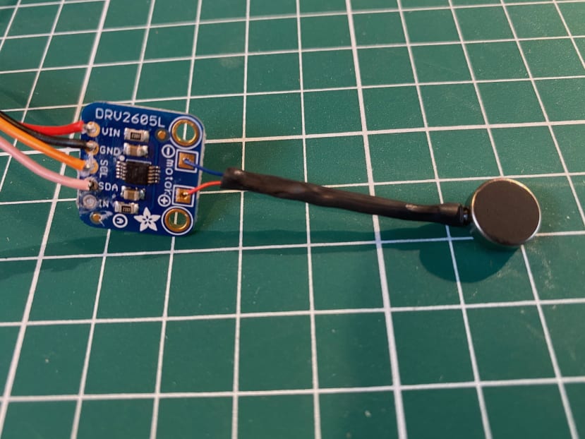
}3) When you're happy that the LED nearest north lights up, connect a vibrating motor to the DRV2605L Haptic controller board. Positive (red) wire from the motor to "+", Negative (in this case, blue) to "-".
I used heat-shrink to protect the wires from the motor.
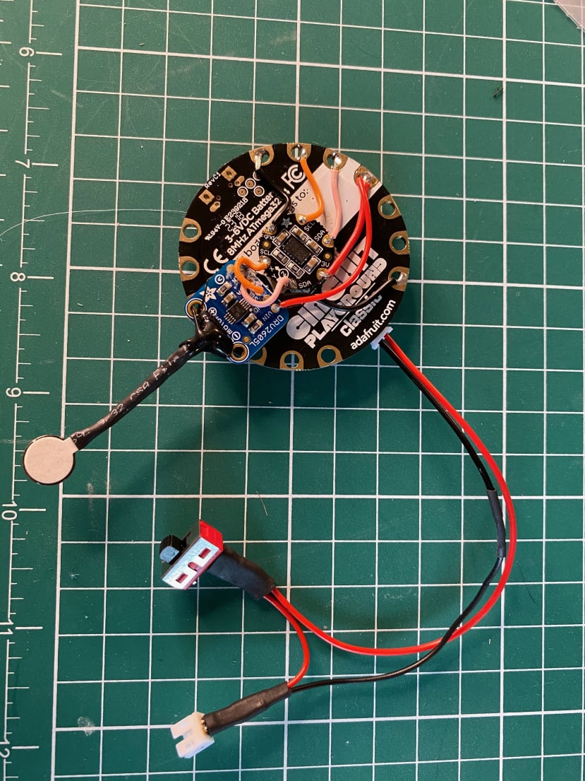
4) Connect the Haptic Controller board to the LSM303 - the wires can be daisy-chained.
- 3V to 3V
- GND to GND
- SDA to SDA
- SCL to SCL
I used hotmelt glue to stick the board to the Circuit Playground, and also to protect the connections of the motor to the controller board.

5) Now for the code - copy and paste the code below into an empty Arduino IDE sketch and upload it to the Circuit Playground. Remember to calibrate the compass!
/* Compass Hat code for The Engineering Edge Podcast

/* This code is based on Adafruit's code (licence and blurb below)
/* with adaptations by Andy Stanford-Clark and Lucy Rogers.
/* Any errors were introduced by Lucy. Sorry.

*******************************************************

/* Circuit Playground Express compass. */

/* Adafruit invests time and resources providing this open source code. */
/* Please support Adafruit and open source hardware by purchasing */
/* products from Adafruit! */

/* Written by Dave Astels for Adafruit Industries */
/* Copyright (c) 2018 Adafruit Industries */
/* Licensed under the MIT license. */

/* All text above must be included in any redistribution. */
*********************************************************
#include <Wire.h>
#include <Adafruit_NeoPixel.h>
#include <Adafruit_Sensor.h>
#include <Adafruit_LSM303_U.h>
#include <math.h>
#include <Adafruit_CircuitPlayground.h>
#include <Adafruit_DRV2605.h>

/* Assign a unique ID to this sensor at the same time */
Adafruit_LSM303_Mag_Unified mag = Adafruit_LSM303_Mag_Unified(12345);
Adafruit_DRV2605 drv;

// Replace these two lines with the results of calibration
//---------------------------------------------------------------------------

float raw_mins[2] = {59.09, -128.45};
float raw_maxes[2] = {100.64, -74.73};
//---------------------------------------------------------------------------

float mins[2];
float maxes[2];
float corrections[2] = {0.0, 0.0};


// Support both classic and express
#ifdef __AVR__
#define NEOPIXEL_PIN 17
#else
#define NEOPIXEL_PIN 8
#endif

// When we setup the NeoPixel library, we tell it how many pixels, and which pin to use to send signals.
// Note that for older NeoPixel strips you might need to change the third parameter--see the strandtest
// example for more information on possible values.
Adafruit_NeoPixel strip = Adafruit_NeoPixel(10, NEOPIXEL_PIN, NEO_GRB + NEO_KHZ800);

// Map direction pie slices (of 30 deg each) to a neopixel, or two for the missing ones at USB & power.
int led_patterns[12][2] = {{4, 5}, {5, -1}, {6, -1}, {7, -1}, {8, -1}, {9, -1}, {9, 0}, {0 -1}, {1, -1}, {2, -1}, {3, -1}, {4, -1}};

#define BUTTON_A 4

void fill(int red, int green, int blue) {
  for (int i = 0; i < 10; i++) {
    strip.setPixelColor(i, red, green, blue);
  }
  strip.show();
}


// Do some initial reading to let the magnetometer settle in.
// This was found by experience to be required.
// Indicated to the user by blue LEDs.
void warm_up(void)
{
  sensors_event_t event;
  fill(0, 0, 64);
  for (int ignore = 0; ignore < 100; ignore++) {
    mag.getEvent(&event);
    delay(10);
  }
}


// Find the range of X and Y values.
// User needs to rotate the CPX a bunch during this.
// Can be refined by doing more of the saem by pressing the A button.
// Indicated to the user by green LEDs.
void calibrate(bool do_the_readings)
{
  sensors_event_t event;
  float values[2];

  fill(0, 64, 0);

  if (do_the_readings) {
    unsigned long start_time = millis();
    while (millis() - start_time < 5000) {

      mag.getEvent(&event);
      values[0] = event.magnetic.x;
      values[1] = event.magnetic.y * -1;
      if (values[0] != 0.0 && values[1] != 0.0) { /* ignore the random zero readings... it's bogus */
        for (int i = 0; i < 2; i++) {
          raw_mins[i] = values[i] < raw_mins[i] ? values[i] : raw_mins[i];
          raw_maxes[i] = values[i] > raw_maxes[i] ? values[i] : raw_maxes[i];
        }
      }
      delay(5);
    }
  }

  for (int i = 0; i < 2; i++) {
    corrections[i] = (raw_maxes[i] + raw_mins[i]) / 2;
    mins[i] = raw_mins[i] - corrections[i];
    maxes[i] = raw_maxes[i] - corrections[i];
  }
  fill(0, 0, 0);
}


void setup(void)
{
  strip.begin();
  strip.show();

  pinMode(BUTTON_A, INPUT_PULLUP);

  /* Enable auto-gain */
  mag.enableAutoRange(true);

  /* Initialise the sensor */
  if(!mag.begin())
  {
    /* There was a problem detecting the LSM303 ... check your connections */
    fill(255, 0, 0);
    while(1);
  }

  warm_up();

  // If reset with button A pressed or calibration hasn't been done, run calibration and report the results
  if (digitalRead(BUTTON_A) || (raw_mins[0] == 1000.0 && raw_mins[1] == 1000.0)) {
    while (!Serial);
    Serial.begin(9600);
    Serial.println("Compass calibration\n");

    raw_mins[0] = 1000.0;
    raw_mins[1] = 1000.0;
    raw_maxes[0] = -1000.0;
    raw_maxes[1] = -1000.0;
    calibrate(true);

    Serial.println("Calibration results\n");
    Serial.println("Update the corresponding lines near the top of the code\n");
    Serial.print("float raw_mins[2] = {"); Serial.print(raw_mins[0]); Serial.print(", "); Serial.print(raw_mins[1]); Serial.println("};");
    Serial.print("float raw_maxes[2] = {"); Serial.print(raw_maxes[0]); Serial.print(", "); Serial.print(raw_maxes[1]); Serial.println("};\n");

    while(1);
  } else {
    calibrate(false);
  }

  // start the buzzer
  drv.begin();

  // set up what a buzz sounds like

  // I2C trigger by sending 'go' command
  drv.setMode(DRV2605_MODE_INTTRIG); // default, internal trigger when sending GO command

  drv.selectLibrary(1);
  drv.setWaveform(0, 84);  // ramp up medium 1, see datasheet part 11.2
  drv.setWaveform(1, 1);  // strong click 100%, see datasheet part 11.2
  drv.setWaveform(2, 0);  // end of waveforms

  // give a little buzz to say we're happy
  drv.go();
}


// Map a value from the input range to the output range
// Used to map MAG values from the calibrated (min/max) range to (-100, 100)
float normalize(float value, float in_min, float in_max) {
  float mapped = (value - in_min) * 200 / (in_max - in_min) + -100;
  float max_clipped = mapped <  100 ? mapped : 100;
  float min_clipped = max_clipped > -100 ? max_clipped : -100;
  return min_clipped;
}


void loop(void)
{
  // Pressing button A does another round of calibration.
  if (digitalRead(BUTTON_A)) {
    calibrate(true);
  }


  sensors_event_t event;
  mag.getEvent(&event);

  float x = event.magnetic.x;
  float y = event.magnetic.y * -1;

  if (x == 0.0 && y == 0.0) {
    return;
  }

  float normalized_x = normalize(x - corrections[0], mins[0], maxes[0]);
  float normalized_y = normalize(y - corrections[1], mins[1], maxes[1]);

  int compass_heading = (int)(atan2(normalized_y, normalized_x) * 180.0 / 3.14159);
  // compass_heading is between -180 and +180 since atan2 returns -pi to +pi
  // this translates it to be between 0 and 360
  compass_heading += 180;

  // We add 15 to account to the zero position being 0 +/- 15 degrees.
  // mod by 360 to keep it within a circle
  // divide by 30 to find which pixel corresponding pie slice it's in
  int direction_index = ((compass_heading + 15) % 360) / 30;

  // light the pixel(s) for the direction the compass is pointing
  // the empty spots where the USB and power connects are use the two leds to either side.
  int *leds;
  leds = led_patterns[direction_index];


  // If LED3 is lit, make a sound and buzz

  if (leds[0] == 2) {
    // buzz the haptics
    drv.go();

    // Make a beep
    delay (50);
      CircuitPlayground.playTone(500, 100);
    delay(50);
       CircuitPlayground.playTone(1000, 500);
    delay(1000);

  }

  for (int pixel = 0; pixel < 10; pixel++) {
    if (pixel == leds[0] || pixel == leds[1]) {
      strip.setPixelColor(pixel, 4, 0, 0);
    } else {
      strip.setPixelColor(pixel, 0, 0, 0);
    }
  }
  strip.show();
  delay(50);
}
6) Hotmelt glueing a Lipo battery directly to a cap isn't a good idea. 3D print a 3.7v 1200mAh lipo battery holder, such as this one by dotcli from Thingiverse: https://www.thingiverse.com/thing:2612451


7) To be able to turn the whole thing off, without having to pull out the JST Lipo battery socket, make a switch (read this article) and connected it.
8) Now it just needs glueing on to the cap and trying it out ...


Note: The delay between beeps was too long when I was walking, and I managed to turn through 90 degrees while trying it out. I am sure this can be improved!
To listen to the main episode visit: Episode 2 - The Everyday Tech Giving Humans a Sixth Sense