Remotely-Controlled Biological Microscope
Follow project
 Dave from DesignSpark
How do you feel about this article? Help us to provide better content for you.
Dave from DesignSpark
Thank you! Your feedback has been received.
Dave from DesignSpark
There was a problem submitting your feedback, please try again later.
Dave from DesignSpark
What do you think of this article?
 When distance does not matter, you can get a seamless experience in visualising your samples. Forget your body strains, you can watch it from your most beloved screens, anytime and anywhere you want. You are always one click away from your result.
Parts list
| Qty | Product | Part number | |
|---|---|---|---|
| 1 | Arduino, Mega 2560 Rev 3 | 715-4084 | |
Most of us had at least used the conventional biological microscope once to observe plant cells and moving microorganisms, and truth to be told, it was great to see these amazing structures. We have been using the microscope occasionally in our undergraduate studies, with backgrounds in Environmental Engineering and Material Science & Engineering, and we realised several inconveniences faced under prolong usage. It all started from gradual strain to pain in the neck, eyes strain from looking through the eyepiece, and the need to stay in the lab to observe the changes in the sample may be very time inefficient.
Our team came together and discussed these issues and how we can make a workaround for the existing microscope. Several things we considered were:
- Is there a way that we can check on the progress without visiting the lab physically? Imagine that you have a growing sample and it takes more than half a day, even up to a few days to multiply. Without having to set time aside to visit the lab, you could use that time for other activities that require more attention.
- How can we make the microscope accessible at any time conveniently? Let's say that our supervisor asks for a quick update on your progress when you just got off the office at the bus stop. Or you are on your way to the lab and got stuck in the morning bustle traffic.
- How can we make a mechanism that could minimise physical contact with these samples? COVID-19 pandemic is extremely detrimental in many parts of the world. Furthermore, we were considering the present and future pandemics where direct contact with the samples poses an extremely high risk to the user.
- We believe that people love to have the autonomy to control. How can we make a microscope that can be remotely controlled by anyone who is granted access? They can have more control of what they want to see and search particularly, and in the case one of the team members missed something important.
With all these considerations, our focus on this project is to modify the existing conventional microscope with a remote control capability to reduce ergonomic issues (back and neck pain) and physical contact between the users and the samples. Before we dive into the nitty-gritty of how the Remote Microscope was designed and made, below is a short video of how the Remote Microscope works.
Our approach
As part of our summer project, we only had 13 weeks to complete the whole setup with minimum technical knowledge. However, it should not be a great hustle for those who have experience in 3D modelling and electronics. For those of you who have spare time and want to try out new things, you should be able to follow along step by step so long as you have the passion to learn. Figure 1 shows the different parts of the Remote Microscope.

Figure 1. Different parts of the Remote Microscope
Microscope & Hardware

Figure 2. Geefuntech Biological Microscope
We purchased a conventional monocular biological microscope to have it modified with our mechanism. A camera module is mounted on the eyepiece and connected to a laptop for imaging purposes. The XY stage will move along their respective axes when the knobs were turned whereas the coarse and fine knobs will remain in their position while the stage was moved up or down. To mechanically control all the knobs, Nema 17 stepper motors were attached through a 3D-printed motor adapter. However, our biggest concern was with the moving knobs of the XY stage. Therefore, we decided to use a flexible soft tube to connect the motor shaft with the 3D-printed adapter.

Figure 3. Soft hose tubing system (old configuration) connected to 3D-printed adapters
We had a major redesign of the adapters (shown in figures 8 and 9 compared to figure 3). Before the redesign, we were only able to achieve a motor precision movement as low as 3 mm (for coarse knob) and 0.6 mm (for fine knob). After the redesign, we were able to achieve lower than 0.1 mm for both coarse and fine knobs. This precision was verified with a magnetic dial indicator set-up as shown in figure 4.

Figure 4. Magnetic dial indicator test
Firmware
We started the project by brainstorming an appropriate mechanism that could control the XY stage, the coarse, and the fine knobs. Looking through the 3D printers available in the lab, we saw spares of RAMPS v1.4, which consists of a Reprap Smart Full LCD Controller, Arduino Mega 2560, and ramps v1.4 shield, which is used to run the 3D printers. Considering this, we saw there is a huge potential in adopting the RAMPS v1.4 into our microscope, especially with the programmable microcontroller to set the speed of the moving motors. We also found that the Marlin firmware loaded into the RAMPS v1.4 can be modified to turn the thermostat off and allow the motors to keep running.

Figure 5. RAMPS v1.4
Software
All the firmware modifications were done in Arduino IDE. Most of the modifications involved calculations to determine the "print bed size" (i.e., the XY stage) and the calibration of the motor turn rate with the steps per unit, feed rate, and acceleration. The model numbers of the motors are also adjusted in the code lines to match the motors used.

Figure 6. Bed size configuration

Figure 7. Calibration of motor turn rate</p
The motor to knob adapters were designed and modelled with Fusion360 and loaded to the 3D printers to extrude out the PLA (polylactic acid) filaments to 3D print the adapters. Several modifications were made to the adapters to strengthen the physical structure and to produce the correct size. These were achieved by adopting the "lock-key" mechanism, where the one end of the adapter fits the shape of the motor shaft to ensure sufficient friction during the turning of the shaft, preventing step-skipping.

Figure 8. Adapter with soft hose tubing

Figure 9. Direct attachment adapter
Initially, we used Pronterface to control the movement of the motors and set shortcuts for commands that are commonly used, such as centering the sample on the XY stage under the objective lens and returning home (as the reset point). However, Pronterface does not support an in-app imaging feature that would provide easier tracking of the slide sample position.

Figure 10. Pronterface interface with pre-uploaded GCode commands
As such, we tried to search for other open-source platforms and we chanced upon OctoPrint. This was exactly what we needed that could complement the features of our Remote Microscope. With an additional 3rd party app called Yawcam, OctroPrint is able to support multiple cameras, with a catch. It requires two open windows desktop to connect to two different camera sources (the first desktop connected to the camera module and the second desktop connected to the laptop webcam), and also to take note of the IP address to enable streaming and connected to OctoPrint for multi-cams support.

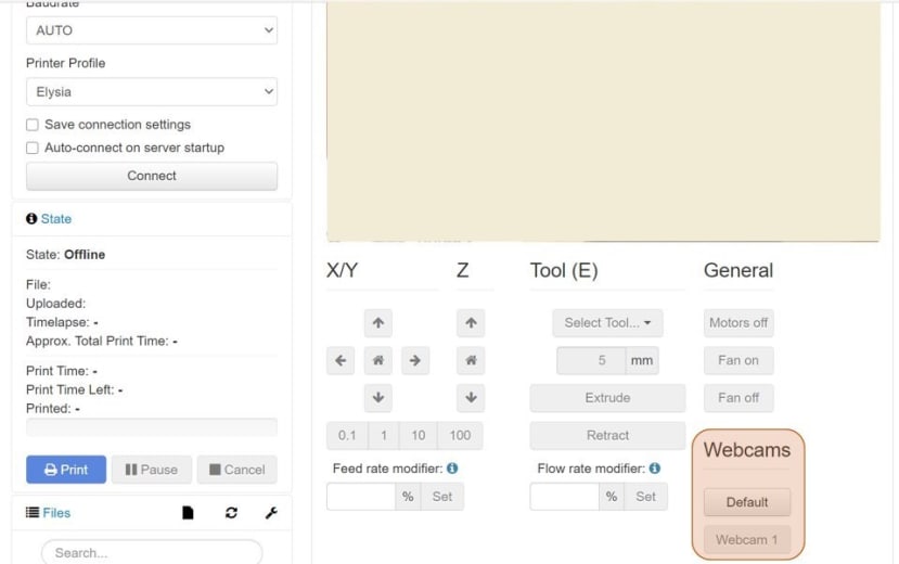
Figure 11. OctoPrint Interface

Figure 12. Yawcam Interface
Lastly, to enable the remote control of the microscope, we utilised TeamViewer to enable remote desktop and with any connected device, the microscope can be controlled remotely anywhere and anytime.
To summarise the whole system, figure 13 shows the process flow diagram to summarise the entire operational process of the Remote Microscope.

Figure 13. Process Flow Diagram of the Remote Microscope
Features
Our Remote Microscope comes with two important features that could potentially improve how microscopes are operated, which we called Live Tracking and Live Monitoring.
Live Tracking
This feature enables the users to manually track motile microorganisms under the microscope remotely by simply navigating the microscope with the available controls in the OctoPrint interface. The video below shows how Live Tracking was done to track the movement of E. coli samples.
Live Monitoring
This feature enables the users to leave their samples for a period of time without the need to be physically present on site. The Live Monitoring system is integrated with a notification system that will alert the users of significant changes that took place within the screen resolution of the imager. Screen Monitor Software is used to detect colour pixel changes on the laptop screen and will notify the users with a customisable notification alert.
Limitations
We had several ideas to develop this Remote Microscope further given the right opportunity, time, budget, and technical expertise. The microscope used can be upgraded to suit the magnification and application requirements, and the relevant hardware changes can be implemented to overcome the hardware limitations.
We found that for a prolonged time, the lens might go out of focus, and image refocusing might take several trials, especially at a higher magnification where minute movements could cause drastic changes. Therefore, an auto-refocus mechanism should be developed to reduce the frustration we might feel and to prevent missing out on important observations during use.
Artificial Intelligence and Machine Learning are the two areas that are of huge development at present. We would like to have these technologies to be implemented in our microscope to aid in the detection and identification of microorganisms and other microscale objects.
Conclusion
Did we manage to address the 4 big questions we listed down earlier in this article? Pretty much we hit the proof-of-concept that our Remote Microscope is able to fulfill the checklists, which are:
- Absolutely convenient. The Remote Microscope can be accessed at your convenience any time of the day. We do not have to be physically present at the lab to check the growth of our samples and dedicate the traveling time to other higher-priority activities.
- Yes, we have designed the Remote Microscope that can be remotely-controlled and thus, minimising physical contact between the users and the samples.
- No, there is no need to be physically present at the lab. The remote desktop is very simple to grant us access to viewing our samples.
- Autonomy requires big responsibility. Users can have the freedom to control the microscope and navigate through the slides, so long as they establish a remote desktop connection with the microscope.
The Remote Microscope could have huge potential in many industrial practices, such as quality assurance (QA), research & development in the medical field, etc., and also in educational sectors, where students are given the chance to have minimal supervision that could promote hands-on interdisciplinary learning between science and technology.
Well, that is all for this Remote Microscope. We hope that all of you readers have a good insight into what can be improved further with our mechanism, especially from experts in this field. We also want this project to become a great source of learning, contribution to the current biotechnology sector, and lastly an inspiration to those who want to start working with new and wild ideas.