Project Valor - Phase 1
Follow project Dave from DesignSpark
How do you feel about this article? Help us to provide better content for you.
Dave from DesignSpark
Thank you! Your feedback has been received.
Dave from DesignSpark
There was a problem submitting your feedback, please try again later.
Dave from DesignSpark
What do you think of this article?
Parts list
| Qty | Product | Part number | |
|---|---|---|---|
| 1 | Carbon Fibre Epoxy Sheet, 300x300x2mm | 764-8716 | |
| 2 | Aluminium Timing Belt Pulley, 10mm Belt Width x 5mm Pitch, 16 Tooth, Maximum Bore Dia. 12mm | 286-5641 | |
| 2 | Aluminium Timing Belt Pulley, 10mm Belt Width x 5mm Pitch, 48 Tooth, Maximum Bore Dia. 60mm | 286-5714 | |
| 2 | Aluminium Timing Belt Pulley, 10mm Belt Width x 5mm Pitch, 20 Tooth, Maximum Bore Dia. 18mm | 286-5663 | |
| 2 | Contitech 10 / T5 / 340 SS, Timing Belt, 68 Teeth, 340mm Length X 10mm Width | 474-5454 | |
| 2 | Deep Groove Ball Bearing 12mm ID 24mm OD | 893-7464 | |
| 1 | RS PRO, M4 Brass Threaded Insert diameter 5.6mm Depth 7.95mm | 278-607 | |
| 2 | Digi International XB24CZ7WIT-004 ZigBee Module +5 dBm, +8 dBm -102 dBm, -100 dBm SPI, UART 2.1 3.6V 24.3mm | 122-5774 | |
| 1 | Contitech 10 / T5 / 355 SS, Timing Belt, 71 Teeth, 355mm Length X 10mm Width | 474-5476 | |
1. Introduction
Project VALOR is a team of five engineering masters students, specialising in mechatronics, biomedical engineering, and management. This was a self-proposed project that will be the start of an ongoing project at the university, as well as being a showcase addition to the annual design show hosted by the university.
NASA has confirmed it aims to have a constant presence on the moon by 2028. Given this, a form of payload transportation should be put in place that can operate over the variable terrains present across the Moon's surface. We plan to design and build a quadruped robot optimised for terrains such as loose regolith, rocky patches, and varying inclines, utilising a four-legged gait. As a team of five masters year engineering students at the University of Southampton, we hope to start this project to serve as a platform for future expansion by the university.
The following article details phase 1 of the project. Phase 1 includes the initial design phase of the quadruped prototype as well as the development of the electronics architecture and control code.
2. Design
2.1 Upper Leg Design
Early in the design phase, we decided to use a pulley system to connect the joints to the motors. In order to house the motors in the shoulder joint, we had to link the actuation to the knee through a belt travelling the length of the upper leg. To do this, we designed a hollow upper leg that allows the belt to be contained within its interior, providing protection. Carbon fibre panels provide the required structural strength of the leg given carbon fibres' high tensile strength and stiffness.
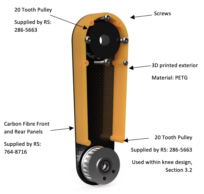
In addition, carbon fibre has high specific strength, i.e it is very light yet strong. This combination of properties means the leg has low inertial mass whilst maintaining a solid construction. This will result in high accuracy of control and resistance to deformation under loading. Given the irregular shape required to fit our design, the carbon fibre will be cut using the water jetting facilities within the University of Southampton EDMC. These panels are linked together through a 3D printed PETG component along their circumference, which seals the belt housing.
2.2 Lower Leg and Knee Design
From preliminary research conducted, it was found that for each gait in which a quadruped can move, a different leg ratio between the upper and lower leg would allow for optimum efficiency. Throughout the course of the project, we will test and implement different gait, hence requiring a variation in leg ratio for optimum performance. This design provides the ability to tailor the leg ratio for each gait, along with conducting further analysis to find the optimum ratios to build upon the information present in existing reports.
The lower leg length can be varied through aligned square cross-section tubes fixed at different heights, as shown below.
The knee below will connect the upper and lower leg through the enclosed belt system previously described. Carbon fibre panels connect the lower leg to the pulley providing drive to the lower limb. The design is shown below.


2.3 Modular Shoulder Design
To increase the robot’s functionality and potential for development the robot has a modular shoulder design. Each modular shoulder encases the motors, encoders and drive mechanism for a single leg of the robot. The modules are then connected by strong and stiff carbon fibre tubes, to ensure there is minimal flexion in the body. A central electronics console is mounted in the middle of the robot to provide power and control to each of the modules. This design has the following benefits:
- Variable footprint of the robot through variation in CF tube length.
- Addition of legs – with slight modification the robot could have more than 4 legs to provide increased stability and strength.
- Simple addition of sensor packs to the existing chassis – Sensors can easily be fixed and removed from the chassis through clip mechanisms depending on the robot’s application.
- Ease of manufacture and repair – The modular nature reduces the number of different components required making repairs easier and manufacture cheaper.
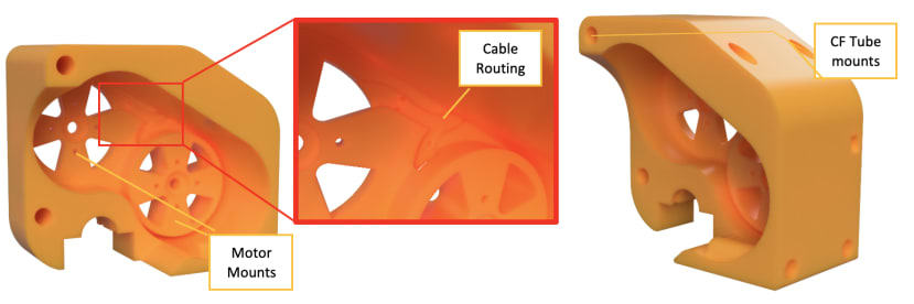
The modular shoulder went through multiple design iterations and the final version is pictured below. Due to its complex shape, the shoulder units will be 3D printed. This also enables us to increase strength in areas of high stress and reduce weight in areas of little stress.
2.4 Concentric Drive Shaft Mechanism
The prime design requirement for the quadruped robot is the need for articulation from at least two points along each leg: hip and knee. This was a mechanism that we knew required a large amount of innovation to ensure the leg remained light and had the greatest range of motion possible. We took inspiration from the coaxial rotor drive mechanisms used in some helicopters, to develop our concentric drive shaft mechanism. The design scheme of this mechanism is described in the following flowchart such that it can be easily followed. Increasing pulley sizes between belts increases the torque delivered to move the leg, making the robot stronger and reducing demand on the motors.

We then went about designing the mechanism pictured below. The design uses aluminium pulleys and bearings supplied by RS Components, all mounted to aluminium driveshafts. The outer shaft is hence mounted to the upper leg (or femur) by M4 bolts passing through the 2 pieces of CF and 3D printed sandwich and into the threaded aluminium flange for maximal strength. The key thing to remember when designing this was to keep manufacturability at the forefront of the design. The whole mechanism is then attached to the shoulder unit of the robot by securing the outer bearings in a housing pictured below.

2.5 Surface Research and Foot Design
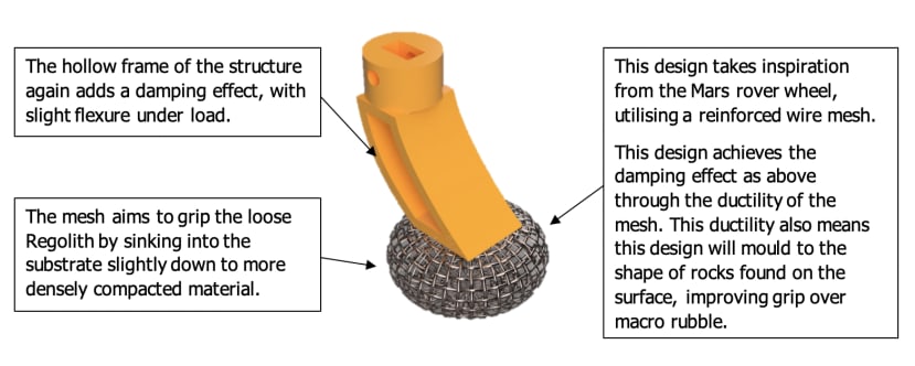
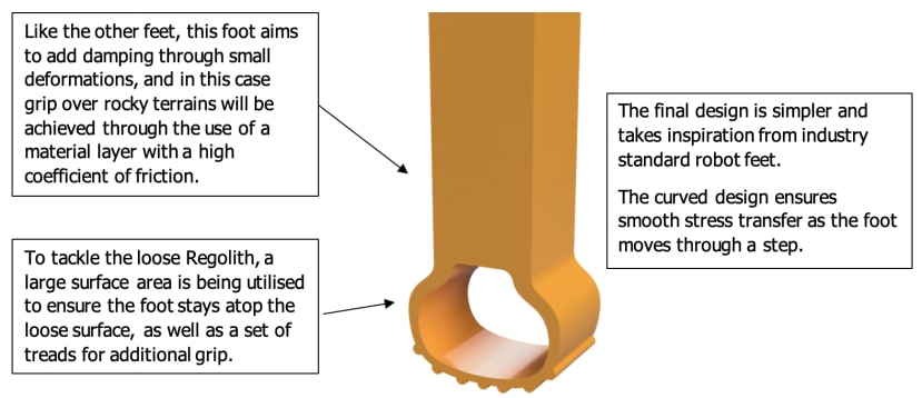
The majority of the accessible lunar surface is made up of a fine dust-like material called Regolith and is on average 3m thick. It comprises a combination of dust, soil, broken rock and is likened to sand. In addition to Regolith, there are rocks of various sizes scattered about the surface and there are varying inclines across the surface. Hence, for our project, our feet must be able to grip the loose substrate of the lunar surface on varying inclines and be able to walk over rocks of various sizes.
We have explored three design methodologies as initial concepts for our feet, each approaching the challenge in a different way:

2.6 Electronic Architecture & Components
To achieve high power, speed, and precision from an actuator; convention suggests a servo motor. However, commercial servo motors are typically not powerful enough for quadruped applications and industrial servos are both very expensive and heavy. The components of a servo motor are simple and relatively cheap with the driver being the most commercially scarce and complex. To actuate our quadruped, we decided on a servo design featuring a high-powered BLDC multirotor motor and an ODrive opensource controller, with position feedback from a high precision magnetic encoder.

As the quadruped is designed for load carrying capability, brushless motors were considered over brushed motors due to their high speed, high specific torque, power density, reliability, and low noise.

A full circuit diagram was based on each ODrive controlling two motors that actuate each leg. The four ODrives are each given signals from a microcontroller which, in this design, was chosen to be a Teensy 4.0. Based on the Arduino architecture, the Teensy operates at 600MHz which is significantly faster than a typical Arduino Uno at 16MHz. This superior core speed should allow for fast code execution which in turn will deliver fast and precise joint actuation.
2.7 Complete Assembly
The full prototype robot render is pictured below. As previously stated, the modular shoulders are connected by carbon fibre tubes to provide stiffness and strength. The full robot measures in at 600x400mm with a max height of 425mm. This provides a large surface area upon which loads can be mounted for transportation.

3. Movement and Control
The quadruped will be required to carry loads across uneven terrains on the lunar surface. We intend to implement this functionality to the robot through precise control of each limb, independent of the other limbs. Control of the limbs will be used to produce movement through a variety of different gaits that will combine the motions of the individual legs. The gaits used within the robot will be configured and implemented in such a way to allow rapid and robust changing between them during robot operation.
3.1 Individual Limb control
Each one of the quadruped’s four legs is controlled by two motors, each operating the hip and knee respectively. The orientation of the hip and knee joints is defined by the angle, theta 1 and 2 respectively. We can control the position of the end effector, the ‘foot’ completely within its workspace by changing just these two parameters. In order to create a movement, we first define a path for the foot to move along and then take samples along this path to create an array of foot positions pertaining to the joint angles. With this position array, we need only define a cycle frequency to move through these positions to achieve motion.
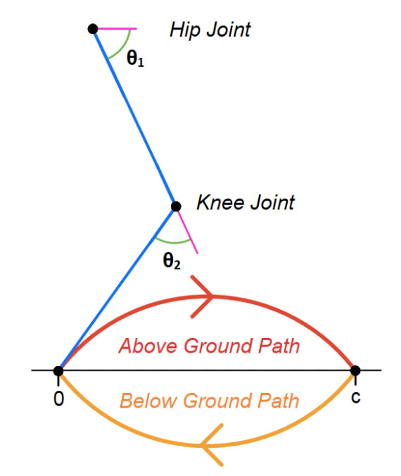
When it comes to creating complex movements like the ones needed to move the robot forwards over the terrain, we can use a compound of two paths, each executed one after the other. To create a walking motion we used an ‘above ground’ path, that would move the foot to a position on the ground in front of its starting position, and a ‘below ground path’, that is the virtual path the foot moves along to exert a force onto the ground without the foot losing contact with it. Executing both paths in sequence moves the robot forwards a distance c while returning the limb to its initial orientation.
3.2 Robot Gaits
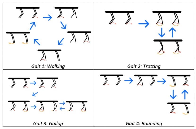
In order to tackle the range of different terrains the robot may encounter on the lunar surface, we have designed several different gaits that can be deployed. All the gaits make use of the compound step movement previously presented but with different cycle frequencies and offsets between the legs. The four gaits we will be including are:
- Walk: The walking gait is the slowest of the four gaits. The robot moves each leg one at a time in sequence executing its above-ground path. All four legs then simultaneously execute their below-ground path moving the body forwards.
- Trot: One back and one front leg from opposite sides work in a pair to perform their step movement simultaneously. The other two legs do the same but 180˚ out of phase.
- Gallop: Each leg performs its step movement with each leg being 90˚ out of phase with the next leg in the sequence.
- Bound: Like the trotting gait but now with the back legs making one pair and the front two legs making the other. The pairs are 180˚ out of phase.
4. Next Steps
To complete phase 1, a single prototype leg module will be manufactured and testing will be conducted in order to validate the existing design, along with refinement and modification in correspondence to the data collected. Testing will be focused around ensuring the design can withstand the required number of life cycles, identifying the stress limits that will be imposed on the quadruped during motion and the temperature ranges experienced within the motors through the operation. After this has been completed, further manufacture of subsequent legs and chassis will follow, leading to full quadruped testing that will inform a 2nd redesign as well as the development of the control code and walking gait control.