
 戴夫来自 DesignSpark
你觉得这篇文章怎么样? 帮助我们为您提供更好的内容。
戴夫来自 DesignSpark
Thank you! Your feedback has been received.
戴夫来自 DesignSpark
There was a problem submitting your feedback, please try again later.
戴夫来自 DesignSpark
你觉得这篇文章怎么样?
 今天我要和大家分享一個裝置——你有多吵鬧!?這個Arduino裝置的LED列陣有助大家了解自身的聲量。
零件清单
| 数量 | 产品 | 库存编号 | |
|---|---|---|---|
| 1 | Grove - Starter Kit for Arduino | 174-3221 | |
| 1 | Parallax Inc 140 mA Servo Motor, 4 → 6 V | 781-3058 | |
| 1 | Ultimaker 3 Dual Nozzle 3D Printer | 124-9474 | |
| 1 | ARDUINO STARTER KIT WITH UNO BRD,K000007 | 761-7355 | |
| 1 | ARDUINO MEGA,A000067 | 715-4084 | |
你有多吵!?
Arduino 聲音,光 和更多更多。
今天我想和大家分享一個裝置——你有多吵鬧!? 我們四周都有一些吵吵鬧鬧的伙伴。可是我們的語氣不能太重當我們提出任何建議時,合適的音量可以使我們的建議更有說服力。今天的分享有利大家準備演講。
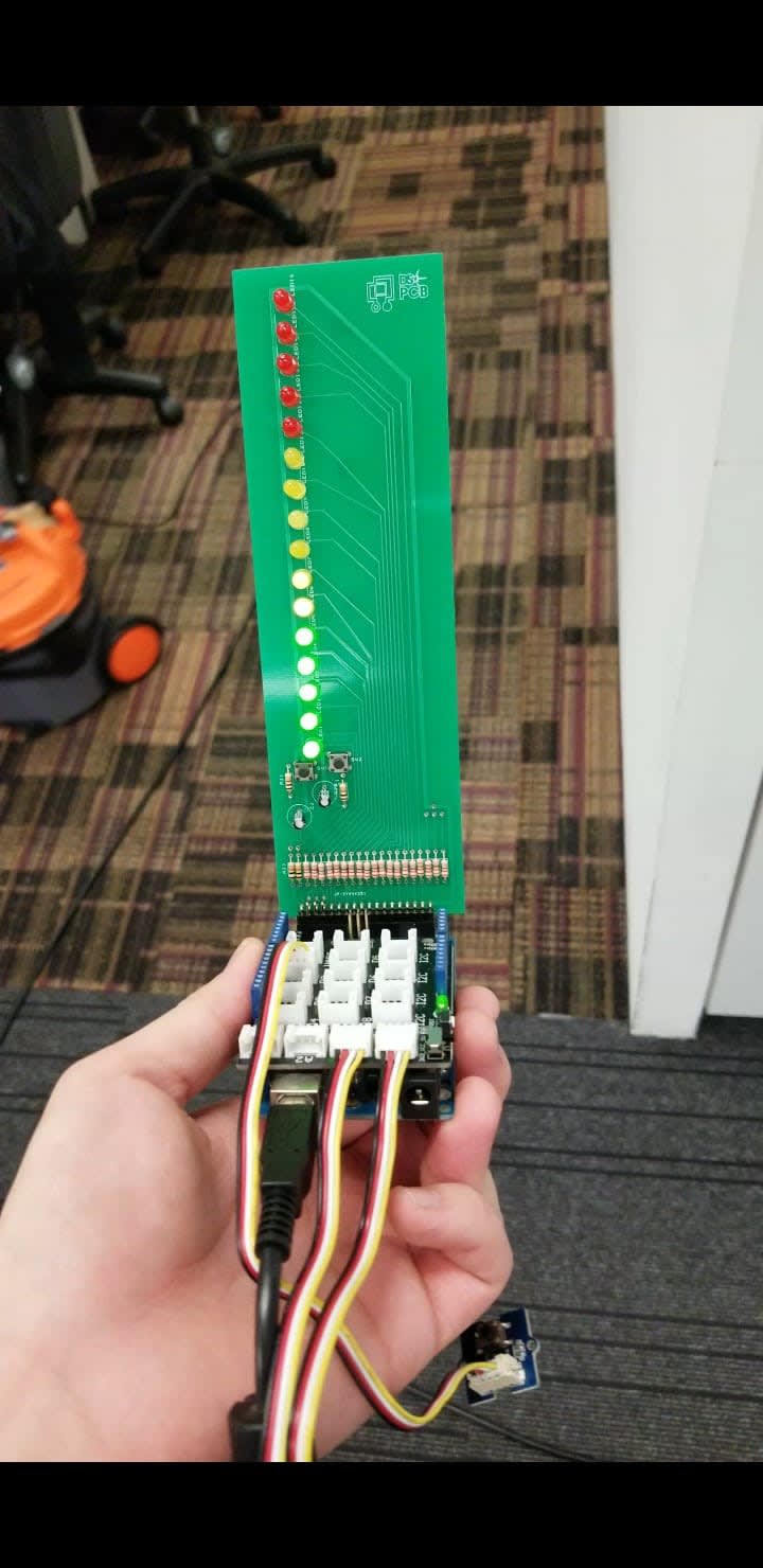
這個裝置的外觀上十分簡單,有LED,Arduino Mega和一些3D打印的東西。
這個裝置的LED列陣有助大家了解自身的聲量。增強我們的說服力。
身體上隱藏著很多微妙的變化,而這些變化是我們不為重視的——體溫。體溫,我們甚少量度,當我們在演講的時候,我們可以手握溫度傳感器,旁邊的紙條捲和筆會開始記錄你的體溫並記錄下來。我們可以了解自己的身體狀況來調整自己的心理狀況。
硬件部分
本分享使用了Arduino Mega、慢轉摩打、3D打印機等等。為什麼我們用上了MEGA 呢? Mega在PIN數上有較多的interrupt,而供電量也大。我們可以伕依賴強大的MEGA同時做不同的工作。使用慢轉摩打來顯示是為了環保。

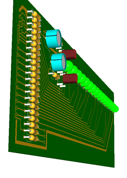
上圖為用DesignSpark PCB 8.1 軟件設計的PCB,這軟件非常有用, 簡易畫出PCB。更多教學按按此。
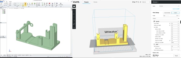
Mechanical software- 3D好幫手,簡單容易上手。更多教學按此。

下圖為最重要的3D打印部分。
軟件部分
第一步我們先引入SERVO 來做INTERRUPT、引入MATH 來計算temperature。
Arduino的小提示,我們會使用const 來控制一些PIN的設定。通常是一些BOOLEAN和ANALOG PIN。
超多PIN的MEGA有6個INTERRUPT PIN。
在PIN8的連接有一個RELAY。
我們設計了3 個模式在3原色燈上分別。
#include <Servo.h>
#include <math.h>                 //for temperature

const int B = 4275;               // B value of the thermistor
const int R0 = 100000;            // R0 = 100k

const byte ledPin = 23;           //tri light
const byte ledPin2 = 27;          //tri light
const byte ledPin3 = 25;          //tri light
const byte interruptPin = 2;      //interrupt
const byte interruptPin2 = 21;    //interrupt

const byte MotorPin = 8;          //motor
volatile byte state = HIGH;       //tri light
volatile byte state1 = LOW;       //tri light
volatile byte state2 = LOW;       //tri light
volatile byte state3 = LOW;       //Servo
void high(int pin)                //LED ON
{ digitalWrite(pin, HIGH); delay(10); }
void low(int pin)                 //LED OFF
{ delay(10);digitalWrite(pin, LOW); }
// Define the pins to which the servo and sensor are connected.
const int pinServo = 3;
const int potentiometer = 0;
const int pinSound = A0;
const int pinangle = A1;
const int pintemp = A2;
int precition=1024;
int Baseprecition=0;
int add=0;
int mi=0;
int degree=0;
// Use a Servo object to represent and control the servo.
Servo AServo;
int thresholdValue = 400;
以下是一些超級有用的界題,我們必須把使用的PINS 設定好PINMODE。我們會使用PINMODE來給予PIN 的工作,一但安排好PIN的工作,我們便不會改動。例如我會使用
(interruptPin, INPUT_PULLUP);// this is not part of the programe來設定interrupt。
所有的輸出PINS 我們必須安排好工務否則便不能正常使用。
我用HARDWARE DEBOUNCED 按鈕來控制INTERRUPT。以下我重複了兩個可以設pin mode 的方法,一是for loop的,二是一個一個的。 For loop 的好處可以節省打CODE時間,但單一case比較專一些。
void setup()
{
   AServo.writeMicroseconds(1500);  // set servo to mid-point
  pinMode(MotorPin, OUTPUT);
   pinMode(ledPin, OUTPUT);
    pinMode(ledPin2, OUTPUT);
     pinMode(ledPin3, OUTPUT);
  pinMode(interruptPin, INPUT_PULLUP);
    pinMode(interruptPin2, INPUT_PULLUP);
  attachInterrupt(digitalPinToInterrupt(interruptPin), blink, CHANGE);
    attachInterrupt(digitalPinToInterrupt(interruptPin2), blink2, CHANGE);

  for (int ok=22;ok<52;ok+=2){pinMode(ok,OUTPUT);}

   pinMode(22, OUTPUT);
    pinMode(24, OUTPUT);
     pinMode(26, OUTPUT);
      pinMode(28, OUTPUT);
       pinMode(30, OUTPUT);
        pinMode(32, OUTPUT);
         pinMode(34, OUTPUT);
          pinMode(36, OUTPUT);
           pinMode(38, OUTPUT);
            pinMode(40, OUTPUT);
             pinMode(42, OUTPUT);
              pinMode(44, OUTPUT);
               pinMode(46, OUTPUT);
                pinMode(48, OUTPUT);
                 pinMode(50, OUTPUT);
                  pinMode(52, OUTPUT);

    // Tell the Servo object which pin to use to control the servo.

    AServo.attach(pinServo);
Serial.begin(115200);
    // Configure the angle sensor's pin for input signals.
    pinMode(potentiometer, INPUT);
}
我喜歡使用FUNCTION來做些重複的動作例如開關LED我寫了HIGH和LOW來操作。
Hello 是記錄LED列陣的。
void loop()
{
   digitalWrite(ledPin, state);
   digitalWrite(ledPin2, state1);
   digitalWrite(ledPin3, state2);
   digitalWrite(MotorPin, state3);


    int sensorValue = analogRead(pinSound)+analogRead(pinangle);
    // Read the value of the angle sensor.
  //  int sensorPosition = analogRead(potentiometer);
 int hello=0;
thresholdValue,sensorValue是兩個獨立的數字用來比較聲量。如果thresholdValue<sensorValue HELLO會記錄好並加上LED 的燈數。
add 是 ++
mi 是 --
if(sensorValue > thresholdValue)    {
  int LLLEEEDDD=22;

  high(LLLEEEDDD);
  LLLEEEDDD+=2;hello+=add;//0
  if(sensorValue > thresholdValue+hello)    {
      high(LLLEEEDDD);  LLLEEEDDD+=2;hello+=add;//1
    if(sensorValue > thresholdValue+hello)    {  high(LLLEEEDDD);  LLLEEEDDD+=2;hello+=add;//2
      if(sensorValue > thresholdValue+hello)    {  high(LLLEEEDDD);  LLLEEEDDD+=2;hello+=add;//3
        if(sensorValue > thresholdValue+hello)    {  high(LLLEEEDDD);  LLLEEEDDD+=2;hello+=add;//4
          if(sensorValue > thresholdValue+hello)    {  high(LLLEEEDDD);  LLLEEEDDD+=2;hello+=add;//5
            if(sensorValue > thresholdValue+hello)    {  high(LLLEEEDDD);  LLLEEEDDD+=2;hello+=add;//6
              if(sensorValue > thresholdValue+hello)    {  high(LLLEEEDDD);  LLLEEEDDD+=2;hello+=add;//7
                if(sensorValue > thresholdValue+hello)    {  high(LLLEEEDDD);  LLLEEEDDD+=2;hello+=add;//8
                  if(sensorValue > thresholdValue+hello)    {  high(LLLEEEDDD);  LLLEEEDDD+=2;hello+=add;//9
                    if(sensorValue > thresholdValue+hello)    {  high(LLLEEEDDD);  LLLEEEDDD+=2;hello+=add;//10
                      if(sensorValue > thresholdValue+hello)    {  high(LLLEEEDDD);  LLLEEEDDD+=2;hello+=add;//11
                        if(sensorValue > thresholdValue+hello)    {  high(LLLEEEDDD);  LLLEEEDDD+=2;hello+=add;//12
                          if(sensorValue > thresholdValue+hello)    {  high(LLLEEEDDD);  LLLEEEDDD+=2;hello+=add;//13
                            if(sensorValue > thresholdValue+hello)    {  high(LLLEEEDDD);  LLLEEEDDD+=2;hello+=add;//14
                              if(sensorValue > thresholdValue+hello)    {  high(LLLEEEDDD);  hello+=add;               //15
                              }low(LLLEEEDDD);LLLEEEDDD-=2;  hello-=mi;
                            }low(LLLEEEDDD);LLLEEEDDD-=2;hello-=mi;
                          }low(LLLEEEDDD);LLLEEEDDD-=2;hello-=mi;
                        }low(LLLEEEDDD);LLLEEEDDD-=2;hello-=mi;
                      }low(LLLEEEDDD);LLLEEEDDD-=2;hello-=mi;
                    }low(LLLEEEDDD);LLLEEEDDD-=2;hello-=mi;
                  }low(LLLEEEDDD);LLLEEEDDD-=2;hello-=mi;
                }low(LLLEEEDDD);LLLEEEDDD-=2;hello-=mi;
              }low(LLLEEEDDD);LLLEEEDDD-=2;hello-=mi;
            }low(LLLEEEDDD);LLLEEEDDD-=2;hello-=mi;
          }low(LLLEEEDDD);LLLEEEDDD-=2;hello-=mi;
        }low(LLLEEEDDD);LLLEEEDDD-=2;hello-=mi;
      }low(LLLEEEDDD);LLLEEEDDD-=2;hello-=mi;
    }low(LLLEEEDDD);LLLEEEDDD-=2;hello-=mi;
  }low(LLLEEEDDD);LLLEEEDDD-=2;hello-=mi;


      Serial.println(sensorValue);

    }hello-=mi;
以下是SERVO的programm我使用了state3來操作SERVO開關。把servo連至pin4
    if(state3==LOW){
      digitalWrite(4, state3);

     delay(15);}
     else if(state3==HIGH){
       digitalWrite(MotorPin, state3);
       digitalWrite(4, state3);
    int a = analogRead(2);

    float R = 1023.0/a-1.0;
    R = R0*R;

    float temperature = 1.0/(log(R/R0)/B+1/298.15)-273.15; // convert to temperature via datasheet

    Serial.print("temperature = ");
    Serial.println(temperature);

     //int sensorValue = analogRead(pinSound)+analogRead(pinangle);


   float shaftPosition = map(temperature, Baseprecition, precition, 1550 , degree);


    // Use the Servo object to move the servo.

    AServo.writeMicroseconds(shaftPosition);

   delay(15);
     }
}
介紹一下interrupt,這裡有兩個interrupt, 分別叫blink 和blink2。
blink是控制3原色燈和各參數的設定
blink2是控制SERVO的設定
void blink() {

    if(state==HIGH){
      thresholdValue = 400;
 Baseprecition=0;
         precition=40;
      degree=2000;
  state = LOW;
  state1=LOW;
  add=50;
  mi=50;
state2=HIGH;}
  else  if(state2==HIGH){
         thresholdValue = 300;
 Baseprecition=0;
         precition=40;
 state = LOW;
 degree=2000;
 add=50;
 mi=50;
  state2=LOW;
  state1=HIGH;}
   else if(state1==HIGH){
         thresholdValue = 200;
         Baseprecition=0;
         precition=40;
         degree = 2000;
  state = HIGH;
  add=50;
  mi=50;
  state2=LOW;
  state1=LOW;}
}
void blink2() {
state3 = !state3;


}
未來發展
看下去好像很無聊,要是我們測量的是地震呢?一個便攜式的地震儀。當然可以大有用途!大家有什麼意見可以在下留言哦,只要我們把思想換一換,便把未來塑做成無盡可能。