Making a Flying Fish Part 1: PCB and 3D Design
Follow article Dave from DesignSpark
How do you feel about this article? Help us to provide better content for you.
Dave from DesignSpark
Thank you! Your feedback has been received.
Dave from DesignSpark
There was a problem submitting your feedback, please try again later.
Dave from DesignSpark
What do you think of this article?
Getting yourself to the core of the controller circuit
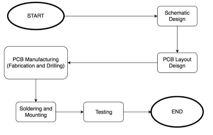
The core of the controller circuit is actually a PCB circuit. Below is the workflow of designing a PCB (printed circuit board), as well as to fabricate it.
I designed this controller circuit using DesignSpark PCB and to make things easier, you can download the PCB file of my design at the bottom of this article and send it to a PCB manufacturer for fabrication.
The attached zip file includes several zip files that contain the gerber and drill files of each of the PCB parts. Please make sure if your manufacturer support 1-zip upload or you shall unzip the master zip and upload each of the child zips individually.

After fabrication, we now have on hand several pieces of PCB and some electronic components like SMD capacitors, resistors, motors, motor driver ICs, etc. We need to consider and choose components carefully as weight control will determine if the final product can fly or not.

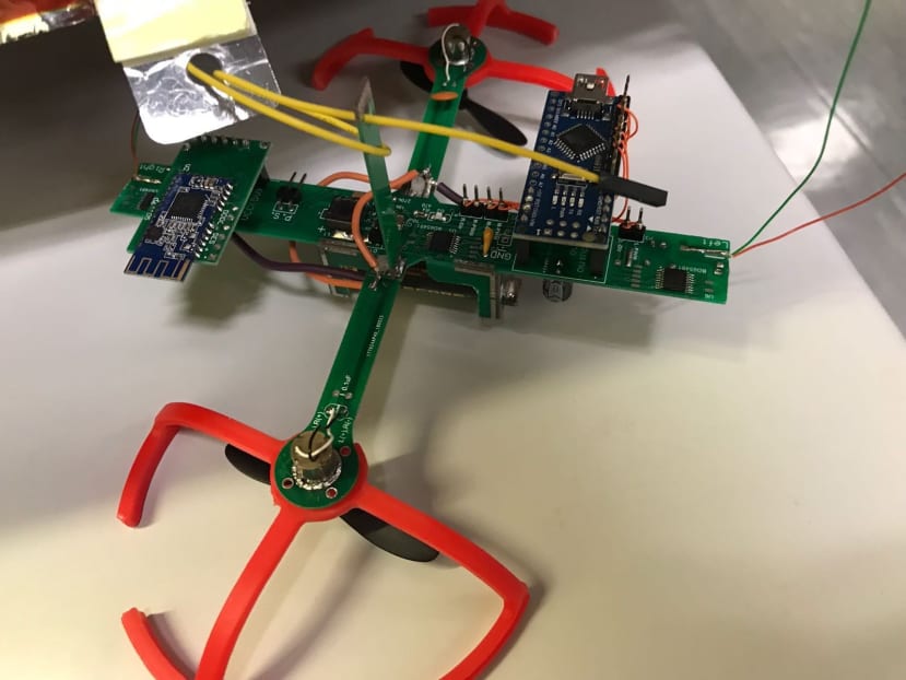
The next thing to do is to place all the components onto the PCBs and connect all the PCBs together as one complete circuit.
I will share the difficulties in the fabrication process and the appearance of the final product in the last article of this series. Stay tuned!
To make your own propeller protector using 3D printing
The software we use for this part is DesignSpark Mechanical, which can be downloaded at https://www.rs-online.com/designspark/mechanical-software (only for Windows).
Before using this free software, you need to create your own DesignSpark account and sign into it.
Now let’s have a closer look into the steps.
First of all, we need to construct the basic skeleton of the protector. And then build up the connection plane that fits the motor radius.
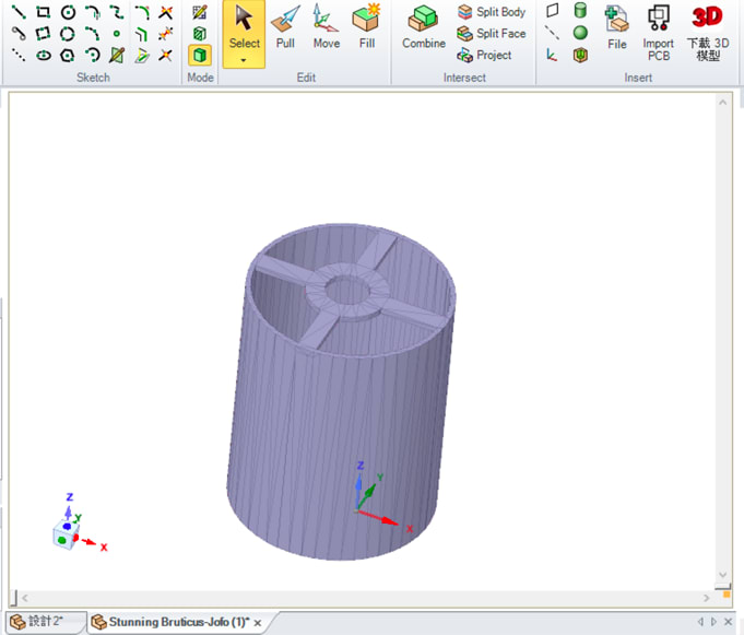
Having completed the design in DesignSpark Mechanical, the next step would be outputting the model file and convert it into a printer-ready file.
In this situation, we are converting it into G-code format using KISSlicer, a free software. You will need to configure for your own situation, for example, if you are using PLA, you will need to change the pre-heat temperature as well as the base thickness, etc. For details, you can make reference to the KISSlicer official manual at http://www.kisslicer.com/uploads/1/5/3/8/15381852/kisslicer_manual_en_201015.pdf
The setting page of KISSlicer is like this:

At the end, probably the easiest part depends on the printer in use. For most of them, just insert your memory stick and start the printing process right away.