How to build an Arduino Robocar Part 2
Follow article
 Dave from DesignSpark
How do you feel about this article? Help us to provide better content for you.
Dave from DesignSpark
Thank you! Your feedback has been received.
Dave from DesignSpark
There was a problem submitting your feedback, please try again later.
Dave from DesignSpark
What do you think of this article?
Pull-up
In the last issue, I mentioned that I would be learning Arduino as I go along and I hacked together a few bits of code that worked almost as expected.
Shameless plug - Part 1
The problem was that I had configured pin A5 as an input, sitting low (0V) and switching on a high level (5V). This in generally bad practice as the pin was floating (not connected to either GND or 5V).
Better practise is to have the pin sit high by using a pull-up resistor and switch to a low signal by connecting it to ground through a switch (or sensor). This is sometimes referred to as steering the pin high.
You can also steer the pin low with a pull-down resistor although this is less common.

Above left is the setup without the resistor and right is the setup with the resistor.
Notice that with the button not actuated (not pressed). The left side does not have a connection to anything and on the right, the input is connected to VCC (+ Voltage). There will always be a small amount of current flowing through the resistor steering the pin to 5V.
When the button is actuated, the pin is connected directly to ground (0V).
This is such an important concept that the Arduino actually has internal pull-up resistors which I will talk about at some point.
The Chassis
Design Spark Mechanical came in really handy here to quickly knock up a body to house all my parts.
If I could give a couple of pointers to using the free tool, make use of the "Plan View" & "Home" buttons when drawing on faces.

Also, always have a look in the bottom right panel for modifiers for the tool you are using.
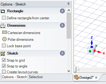
Above note the "Define rectangle from centre" which can be very useful at times!
The design
Here's what I ended up with:

The front cut-out is for a stepper motor (892-8723) to actuate the steering left & right:
Although the one I'm using is salvaged from an old 3D printer so please check the dimensions if you intend to use that one.
The two holes up front are for the bumper system (TBC).
The side cut-outs are for the Microswitches (776-8551) that will let the car know it's crashed (via the bumper system)
Awesome little changeover switch that can handle 15 Amps!
The rear channelled section is for the drive motors (238-9759)
Check sizing if using above.
(238-9838) Should work well although I'm using two salvaged motors.
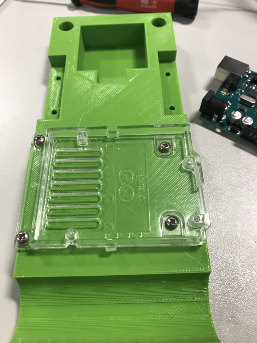
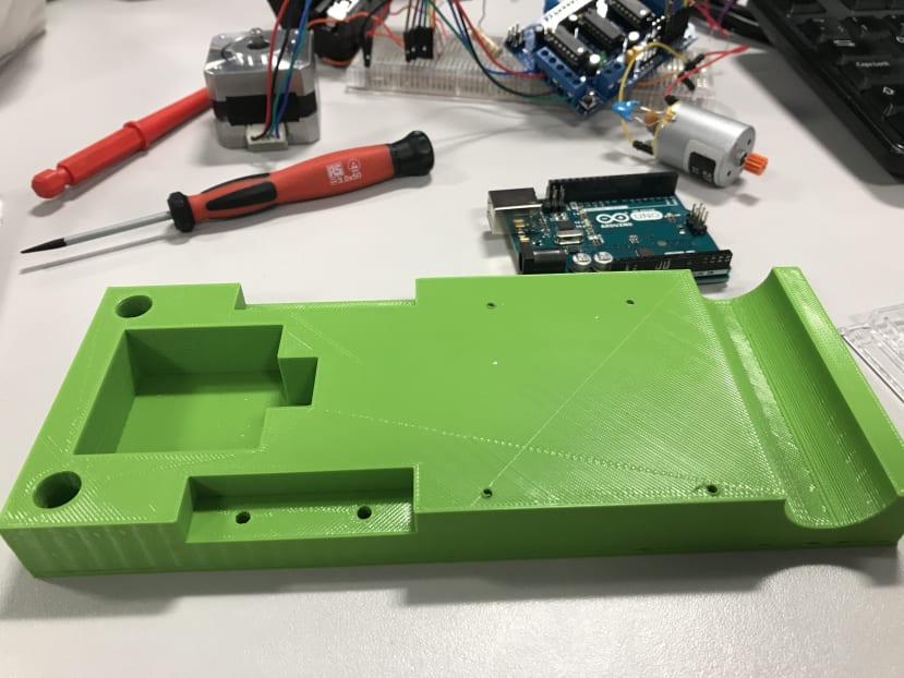
Here's some photo's of the assembly process and the finished part.

Next up....
Next time I'll be talking about the code that will get the wheels spinning and the collisions happening.
I also need to start thinking about the bumpers and wheels.
You choose the colours....
I'm running a poll, I currently have:
Purple, Black, Pink, Green, Blue and White filament available, so post your choice for the front steering axis in the comments below and most votes for any colour gets it!
Next time I'll poll for the wheel colours.
Stuart