Getting Started with the STMicroelectronics STM32L4+ Discovery Kit
Follow article
 Dave from DesignSpark
How do you feel about this article? Help us to provide better content for you.
Dave from DesignSpark
Thank you! Your feedback has been received.
Dave from DesignSpark
There was a problem submitting your feedback, please try again later.
Dave from DesignSpark
What do you think of this article?

The B-L475E-IOT01A Discovery kit allows users to develop applications featuring direct connection of wireless IoT sensors to cloud servers. It is supported by a wide range of Integrated Development Environments (IDEs) including IAR™, Keil® and GCC-based IDEs.
The Discovery kit enables a wide diversity of applications by exploiting low-power communication, multiway sensing, support for Arduino Uno V3 and PMOD connectivity provides unlimited expansion capabilities with a large choice of specialized add-on boards.
The STM32L4 Arm Cortex-M4 core base variance of applications necessitating low-power communications.

Fully loaded low power multi-facet STM32 communication development platform.
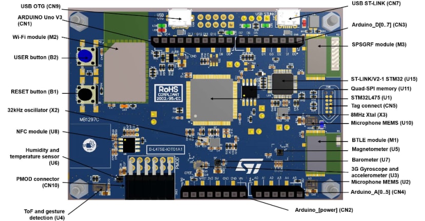
STM32L4 Discovery kit IoT node PCB (top view)
Featured products.
B-L4S51-IOT01A IoT node offers multi-channel communications with the STM32L4
Board Features
STM32L475VG low-power Cortex-M4 core MCU with 1MB Flash memory, 128KB SRAM
- On-board MX25R6435F 64Mbit Quad-SPI Flash memory
- On-board ST-LINK/V2-1 debug/programmer via USB micro-AB socket
- On-board SPBTLE-RF Bluetooth 4.1 RF module
- On-board SPSGRF 868MHz (RS 134-5559) or 915MHz (RS 134-5558) RF module
- On-Board ISM43362-M3G-L44 WiFi RF module (IEEE 802.11 b/g/n compliant)
- On-board M24SR64-Y Dynamic NFC tag with PCB antenna
- 2 x MP34DT01 MEMS microphones
- HTS221 Relative Humidity and Temperature sensor
- LIS3MDL 3-axis Magnetometer
- LSM6DSL 3-axis Accelerometer/Gyroscope
- LPS22HB 260-1260hPa Barometer
- VL53L0X Time-of-Flight and Gesture-Detection sensor
- Reset pushbutton
- Wake-Up/User pushbutton
- 2 x User LEDs
- USB OTG FS via micro-AB socket
- Arduino v3 Shield connectors
- Pmod™ 12-pin expansion connector
- Power supplies: USB STLINK, USB FS, Arduino, USB Charger or Battery
- ARM mbed™ -Enabled (see http://mbed.org)
- On-board ST-LINK/V2-1 debugger/programmer with USB re-enumeration capability: mass storage, Virtual COM port and debug port.
- Comprehensive free software HAL library including a variety of examples, as part of the STM32Cube MCU Package.
- Support of a wide choice of Integrated Development Environments (IDEs) including IAR™, Keil®, GCC-based IDEs, Arm® Mbed Enabled™.
Evaluation Kit:
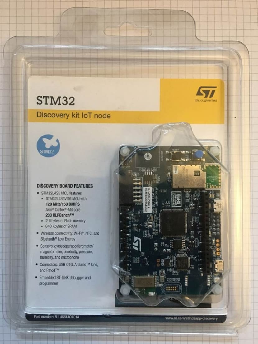
The STM32 Discovery kit IoT node B-L4S51-IOT01A2 (134-5559) B-L475E-IOT01A2 with 868MHz RF module

Type A to Micro-B cable required, but not included in the kit (790-3662)
Out of the box demo of the WiFi HTTP Server (Windows platform):
Powering up the board:
- Connect Micro USB cable to USB STlink connector to your host PC USB Type-A connector.
- Load and run Tera Term. Configure the comms port and baud rate, number of bits, stop bits, parity and handshaking.
Code snippet: UART configuration as per the installed application code:
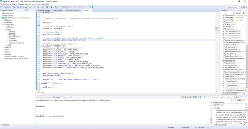
Software overview of the preinstalled flashed, shipped with the Wi-Fi Web Server demonstration code example.
The ST WiFi Web Server needs to connect to your local Wi-Fi router therefore the following network details are required:
Your Network Router configuration details:
- SSID
- Password
- Security options:
- WIFI_ECN_OPEN,
- WIFI_ECN_WEP,
- WIFI_ECN_WPA_PSK,
- WIFI_ECN_WPA2_PSK.
The network details will be stored in non-volatile memory, facilitating booting to the same network.
It is possible to reset the Wi-Fi router login details by holding down the blue button #2 for 5 seconds immediately after power-up.
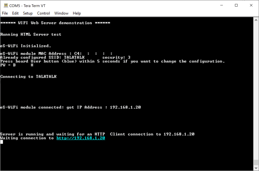
When the USB cable is connected, Tera Term configured, power is applied and stabilized press the Reset black button B1.
The example Wi-Fi Web Server Demonstration system initialization boot sequence is detailed and presented on Tera Term, shown in the example below.
Security is set to WIFI_ECN_WPA2_PSK: ( I have removed my login details )
The Wi-Fi Server is running and thus awaiting a connection to a Web Brower pointing to http://192.168.1.20.
Launch your favourite web browser and enter the presented Wi-Fi server IP address into the browser address field.
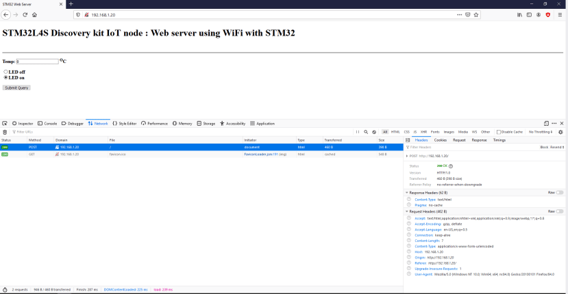
Browser web developer > Network (option actioned)
Retrieving the on-board temperature value from the Wi-Fi Web server sensor:
To action the web client, click on the submit button, the development kit temperature will be retrieved from the Web Server and the LED radio button status will be sent to the Web Server LED port.
To turn on the green LED (LD2) click on radio button LED on and then click on the Submit Query button. The Green LED (LD2) is now on as shown in the picture below:

Code Snippet

Function: SendWebPage(), Formats the HTML code and memory buffer for transmission over the Wi-Fi link.
HTTP Get & Post methods are used for Client and Server data transfer

Wrapping up
The B-L475E-IOT01A Discovery kit is an excellent complex IoT development board and a great IoT platform. I modified the HTML code to add an additional field, initial syntax issues with formatting the HTML using the strcat function but works well. The software stack is present and documented very well.
For quick evaluation of system timings, capturing boot and system initialization timing plots etc I would like to have easy access to the Wi-Fi module’s data and control signal; header pins or solder pads.
Terminal Emulation:
I experienced issues using PuTTY for terminal emulation, concatenation of control characters within the password string suffix.
For additional details please see:
- STM32L4 Product Page
- STM32L4 User’s Manual
- STM32L4 B-L4S51-IoT01 Schematics
- STM32Cube IDE
- STM32L4 Tools & Software Examples
— Richard Seymour