Drive an I2C DAC with C++ on IOT2020
Follow article Dave from DesignSpark
How do you feel about this article? Help us to provide better content for you.
Dave from DesignSpark
Thank you! Your feedback has been received.
Dave from DesignSpark
There was a problem submitting your feedback, please try again later.
Dave from DesignSpark
What do you think of this article?
How to control an I2C DAC with the IOT2020.
The program is based on Siemens' SIMATIC IOT2000 I2C example LED and Peter Oakes' Arduino article.
How it works
The example is simple. A buffer holds 256 samples of a sinus signal.
Our code loops trough that buffer and sets the DAC to each of the values. Forever.
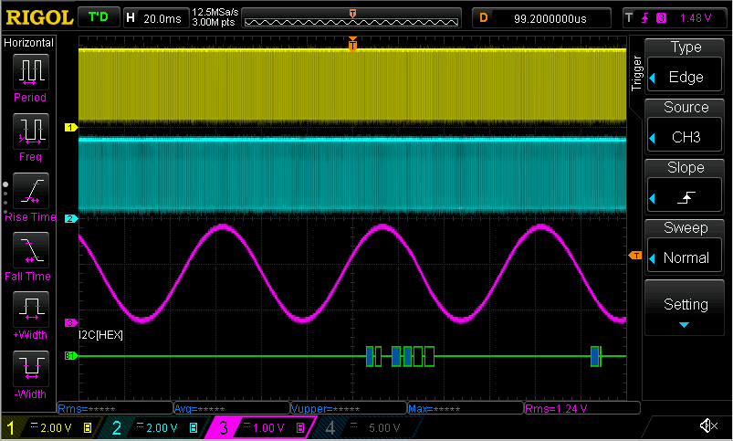
The result is a sinus signal on the output of the DAC.
The DAC talks I2C. So each of the buffer values is sent to the DAC8571 via that protocol.
|
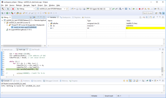
#include uint16_t Sin_tab[256] = { 32768, 33572, 34376, 35178, 35980, 36779, 37576, int main() { i2c = new mraa::I2c(0); while (1) { |
- 0x4C is the I2C address of the DAC.
- buffer[0] contains the value 0x10 - adapt output to payload immediately
- buffer[1] contains the high bits of the 16 bit value
- buffer[2] the low bits.
Hardware
You need two I2C pull-up resistors (1K5) and the DAC8571.
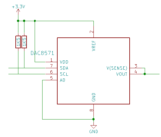
Connections with IOT2020 Arduino headers
- 3V3 to X13.P4
- GND to X13.P6
- SDA to X10.P9
- SCL to X10.P10

Connections for Oscilloscope
Attach one of your oscilloscope probes to the DAC output, it's alligator clip to GND.
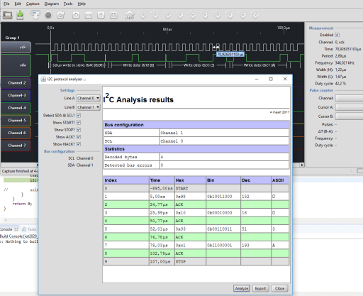
You can also hook up a protocol analyser and check the traffic.
The Source code is attached.
Happy I²C-ing