Developing your own Flowcode 7 controlled weather station
Follow article
 Dave from DesignSpark
How do you feel about this article? Help us to provide better content for you.
Dave from DesignSpark
Thank you! Your feedback has been received.
Dave from DesignSpark
There was a problem submitting your feedback, please try again later.
Dave from DesignSpark
What do you think of this article?
This project details a Flowcode and E-blocks based weather station capable of reading local temperature and humidity with 2 remote thermo-hygrometer sensors. The local board also incorporates a real time clock. This article has been contributed by Flowcode user John Crow.
Flowcode can be downloaded and trialled for free at the Matrix Technology Solutions website. You can also purchase Flowcode licences through the RS website.
Introduction.
Flowcode V7 has (along with many other new features) a macro to use the nRF24L01 2.4 GHz RF Transceiver.
It was this component that inspired me to develop this project.
I should point out this project is only compatible with Flowcode 7 as the nRF24L01 component is not included in earlier versions.
Also the component is used under the ISM (industrial Scientific and Medical Licence) and can be used freely for experimentation without the need to obtain a formal licence.
The board may suffer from interference from microwave ovens as they are on a similar frequency.
The project assumes the user is familiar with the basic use of Flowcode and E-Blocks.
PART 1 Remote Sensor.
The remote sensors use identical hardware, and the only difference in the program loaded is the value of Sensor_ID, either 1 or 2. This is set in the Flowcode program.
Equipment Required. (Per Sensor)
- EB-006 V9 Multi-programmer (Fitted with 16F1937)
- EB-005 LCD E-Block
- EB-016 Proto-Board
- Power Supply (9V DC)
- nRF24L01 RF Module (With suitable aerial) (Sparkfun)
- HTU21D (SHT21 Sensor) Temperature / Humidity Module (Adafruit)
- Jumper Wires (To connect the E-Blocks power)
The RF and Temperature Sensors can be sourced from several places
I have just named the type I’m using.
RS also supply a Thermo-Hygrometer board using the SHT21 sensor. (EBM016)
Connections.
Port B - EB-005 LCD Display.
This gives a local reading of the temperature and humidity data being transmitted.
Both the Thermo-Hygrometer Sensor and the RF Board are plugged into the EB-016 Prototype board, and connected to Ports C & D
Port C - nRF24L01 RF Module.
Hardware Setting Channel 1
- Port C2 CE
- Port C3 SCK
- Port C4 MIOS
- Port C5 MOSI
- Port C7 CSN
- Port D0 Transmit LED Via 330R Resistor to ground.
This module has a 3.3v regulator on board so can be connected directly to the 5V supply from the EB-006.
Cheaper (E-Bay) modules are often only 3.3V so care must be taken when connecting them up.
Port D - HTU210 Thermo-Hygrometer.
This uses the I2C Bus to connect to the microcontroller.
Software setting
- Port D4 SDA
- Port D5 SCL
Power is taken from the 5V supply on the EB-006.

Remote Sensor Board
Both remote sensors use the same hardware.
The small read board is the nRF24L01 RF Board, the board to the right is the HTU21D Thermo-Hygrometer Sensor.
Operation.
The beauty of building a project with Flowcode is the ease with which complex sensors such as the nRF24L01 and the HTU21D used in this project can be added, with just a few icons in the flowchart.
The flowchart operates as follows
- Initialising the nRF24L01 and the LCD modules
- Read Temperature from the HTU21D as an integer
- Read Humidity from the HTU21D as an integer
This is then displayed on the LCD board.
The data is read as an integer because although the HTU21D can support floating point variables, the nRF24L01 can only transmit 8 bit bytes.
An ID value is first allocated to the sensor. This allows the data to be identified when received by the local board.
For this project sensor 1 has an ID=1 and sensor 2 has an ID=2.
To transmit the data it is loaded into a FiFO (First In First Out) buffer, with each variable having an ID Byte
- Byte 0 = Sensor_ID
- Byte 1 = Temperature
- Byte 2 = Humidity
The buffer can support up to 32 bytes of data.
The buffer is then transmitted to the local board.
Once transmitted, Port D0 is sent high for 500 ms to illuminate the Tx LED. It is then sent low to turn the LED off again.
A short delay of either 1 second (sensor 1) or 2 seconds (sensor 2) is added, followed by a extra random delay to add a few more microseconds to the whole loop.
This is to minimise the chance of both boards trying to transmit at the same time.
However, with temperature and humidity data, this will not cause any critical errors as the sensor readings will not be changing very rapidly.
PART 2 Local Board With LCD Display
Introduction.
This board displays the temperature and humidity alternately from the 2 remote sensors on a 4 x 20 line LCD display to show the temperature and humidity data. It also shows the approximate dew point temperature.
- Line 0 shows the Sensor_ID
- Line1 shows Temperature
- Line2 shows Humidity
- Line 3 Shows Dewpoint
As explained in the remote board section, the data displayed depends on the value of the Sensor_ID transmitted.
A Real Time Clock using a DS1307 is displayed on a second LCD Display.
Equipment Required.
- EB-006 V7 Programmer (Fitted with PIC 16F1937)
- EB-016 Proto-Board
- Power Supply (12V DC)
- EB-005 LCD Display
- nRF24L01 RF Module (With suitable aerial) (Sparkfun)
- HTU210 (SHT21) Temperature / Humidity Module (Adafruit)
- Custom LCD Display (4x20 )
- DS1307 RTC Breakout Board (Adafruit)
- Ribbon Cables (M-F)
- Jumper Wires (To connect the E-Blocks power)
Note: The V7 Programmer needs a 12V supply. An EB006 V9 may be used if available.

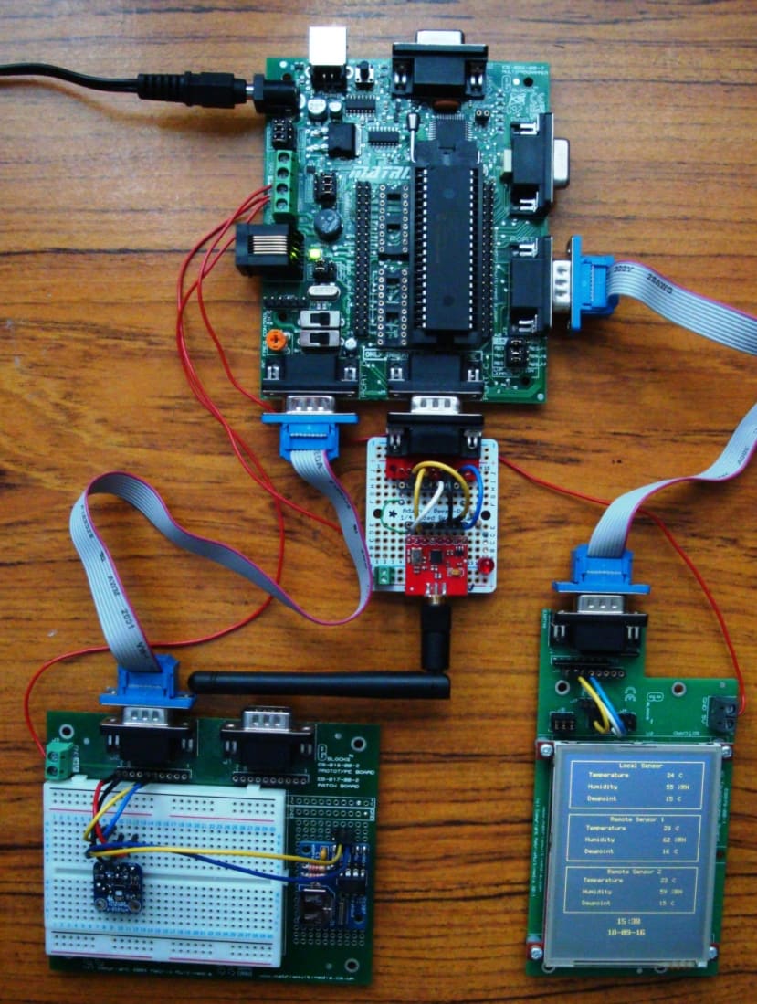
Local Board (LCD Display) Full System
As seen from the photographs, I have built a customised E-Block with the nRF24L01 sensor on this part of the project.
This is configured using the same type of “Patch System” built into most E-blocks.
The LED on the RF board is not used in this part of the project.
The HTU21D Thermo-Hygrometer is plugged into the patch board
The DS1307 RTC board is the one to the right of the patch board, and is soldered to the prototype area. Power connections are run underneath the Patch Board to the 5V power rails.

DS1307 Real Time Clock
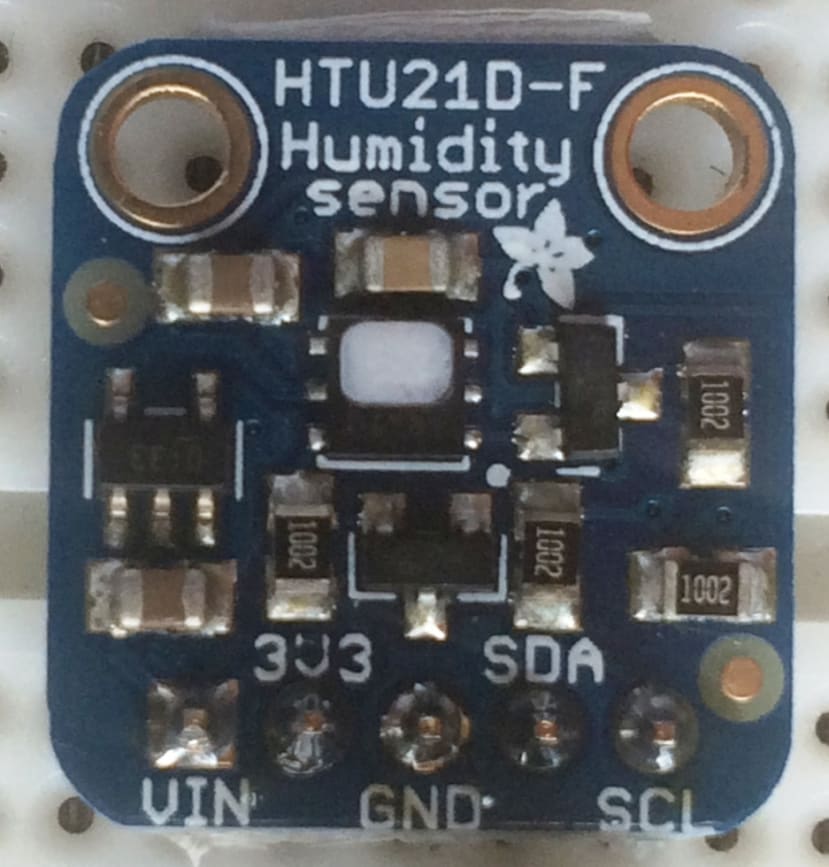
HTU 21D Thermo-Hygrometer Sensor

Local Board LCD Display showing Local Sensor Readings

nRF24L01 RF Board with Patch System
Connections.
Port A - EB-005 LCD Display
This shows the time & date from a DS1307 RTC device.
Port B - Custom LCD Display
This uses a standard 4 x 20 LCD display, using the same connections and control chip as the Matrix EB-005 LCD
Port C - nRF24L01 RF Module
Hardware Setting Channel 1
- Port C2 CE
- Port C3 SCK
- Port C4 MIOS
- Port C5 MOSI
- Port C7 CSN
Full information on the nRF24L01 device can be found at
http://www.nordicsemi.com/eng/Products/2.4GHz-RF/nRF24L01P
Port D - DS1307 RTC
The I2C port setting needs to be changed from the default setting in the component.
I2C Software Setting
- Port D4 SDA
- Port D5 SCL
The RTC component is not part of the default installation of FC7, and has been produced by a Matrix TSL customer “Jordy” and can be downloaded from the Matrix forums.
This component always resets to its default address on Port C when saving the flowchart. When loading the flowchart into Flowcode it needs to be set to the I2C address setting above, before sending the file to the PIC.
The chip will need to be loaded with the correct data before being used in this project.
The breakout board I’m using has a battery backup, so data is retained for several years once set.
Port D – HTU21D Thermo-Hygrometer Sensor
I2C Software Setting
- Port D4 SDA
- Port D5 SCL
Operation.
The flowchart operates as follows.
- After initialising the various modules, the program goes into a loop.
- Read the time and date from the RTC and display on the 2 line LCD.
- Read the temperature & humidity data from the local sensor.
- Check for a signal from the RF board.
- If no signal is detected, then display “Remote Sensor Failure”.
- Check if the signal is from sensor 1 or 2.
- Read sensor temperature and humidity data.
- Calculate Dewpoint.
- Display data on the 4 line LCD.
- Short Delay.
- Clear LCD and go back and read next set of data.
If one sensor fails, the display just keeps showing the working one. However if both remote sensors fail, A “Remote Sensor Failure” message is displayed.
The message may not show for a few seconds after failure until the Rx buffer has been emptied
DewPoint.
A simple explanation of Dewpoint:
The Dewpoint temperature is the temperature to which air must be cooled in order to reach full saturation.(i.e. it cannot hold any more moisture).
To calculate dewpoint accurately needs a fairly complex calculation, which is beyond the scope of this article.
An approximate method is used in this project.
Dewpoint = Temperature – ((100 – Humidity)/5)
PART 3 Local Board With VGA Display
Introduction.
The main problem with the LCD display used in part 2, is it can only show the data from one sensor at a time, and needs a second display for the RTC.
Using the EB-076 VGA display, all the information can be seen at one time, and it can be laid out in a neat easy to read format.
The most significant disadvantage of the display is it costs significantly more than the two LCDs used in part 2.
Local Board (VGA Display) Full System

EB-076 Display
The 3 boxes and text are added at the beginning of the program before the start of reading the data from the sensors.
This means only the temperature, humidity and real time clock data has to be changed during the program execution.
Connections.
The EB-076 is connected as follows. Jumper to PATCH setting using short cables connect the patch connections as below.
- Port B7 RX
- Port B6 TX
- Port B5 Reset
All other hardware connections are as in part 2.
Part 4 Flowcharts.
The flowcharts are loaded into hardware as below
- Remote_Sensor1.fcfx = Remote Sensor 1
- Remote_Sensor2.fcfx = Remote Sensor 2
- Local_Board_LCD.fcfx = Local Board (LCD Display)
- Local_Board_VGA.fcfx = Local Board (VGA Display)
Part 5 Bill Of Materials.
A full list of parts to complete this project.
- 3 x EB006 Programmer – Fitted with PIC 16F1937 Devices.
- 2 x EB005 LCD Display.
- 3 x EB-016 Prototype Board.
- 1 x EB076 VGA Display Board.
- 3 x Matrix Power Supply.
- 1 x Custom 4 x 20 LCD Display.
- 3 x HTU21D Thermo-Hygrometer Break Out Boards.
- 3 x nRF24L01 RF Boards (Spakrfun) – With Aerial.
- 2 x M- F Ribbon Cable.
- 2 x Red LED.
- 2 x 330R Resistor.
- 3 x M- F Patch Leads.
- 32 x M-M Patch Leads.
- Flexible Multi-Strand Cable to connect power to e-blocks from the programmer.