Detection Techniques of SMD Diodes
Follow article Dave from DesignSpark
How do you feel about this article? Help us to provide better content for you.
Dave from DesignSpark
Thank you! Your feedback has been received.
Dave from DesignSpark
There was a problem submitting your feedback, please try again later.
Dave from DesignSpark
What do you think of this article?
In engineering technology, the internal structure of the SMD diode is basically the same as that of a general-purpose diode, both of which consist of a PN junction. Therefore, their detection methods are basically the same. For the detection of the SMD diode, the “R×100 Ω” gear of the multimeter is usually used.
Detection of SMD Diodes
1. Identification of positive and negative electrodes
The identification of the positive and negative poles of an SMD diode can be observed by the casing. When the mark on the casing is severely worn out, we can use a multimeter for identification. The detection diagram is shown in Figure 1.
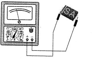
Figure 1
Set the multimeter to the gear of “R × 100 Ω” or “R × 1 kΩ”. First use the red and black test leads of the multimeter to randomly measure the resistance between the two pins of the SMD diode, and then exchange the two test leads for another measurement.
In the two measurement results, the one with the smaller resistance value indicates that the SMD diode has a forward resistance (generally several hundred to several thousand ohms), with the black test lead connected to the positive pole and the red test lead connected to the negative pole. While the other result with a larger resistance shows that the SMD diode has a reverse resistance (generally several tens of kilohms to several hundred kilohms), with an opposite connection of the test leads to the first one.
2. Judging the Performance
The detection of the performance of SMD Diodes is usually carried out in an open state (away from the circuit board).
Use the “R × 100Ω” or “R × 1 kΩ” gear of the multimeter to measure the forward and reverse resistance of the SMD diode. According to the unidirectional conductivity of the diode, the greater the difference between the forward and reverse resistances, the better the unidirectional conductivity will be. If there is little difference between forward and reverse resistances, it means the performance of unidirectional conductivity of the SMD diode is deteriorated; if the positive and negative resistances are both large, the SMD diode has an open circuit failure; if the positive and negative resistances are small, the patch diode has failed. When the above three conditions occur in the SMD diode, it must be replaced.
Detection of Special SMD Diode
1. Detection of Voltage Regulation SMD Diode
(a) Discrimination of Positive and Negative Poles
The pin of voltage regulation SMD diode is also divided into positive and negative poles as the general-purpose SMD diode, which can generally be identified according to the mark on the package, such as the diode symbol, the length of the lead, color wheels, color spots. If the mark on the package is worn out, it can also be measured by a multimeter. The method is the same as the detection of the general-purpose SMD diode.
(b) Judging the Performance
The method is the same as that of a general-purpose SMD diode. Normally, the forward resistance is about 10 kΩ, and the reverse resistance is infinite.
(c) Measurement of the Voltage RegulationValue
The method is shown in FIG. 2
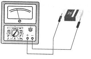
In Figure 2, the multimeter is set to the “l0 kΩ” gear, the red and black test lead is connected to the positive and negative pole of the voltage regulation SMD diode. After the multimeter pointer is deflected to a stable value, read the value that the pointer points at the scale of the “DC10” gear. Then calculate the steady voltage regulation value of the Zener diode according to the following empirical formula:
voltage regulation value Uz=(10 - reading value) × 15 V
This measuring method can only measure the voltage regulation SMD diode with the voltage regulation value that is below the cell voltage used in the high gear of the multimeter.
2. Detection of light-emitting SMD Diode
The Identification of Positive and Negative Electrodes
Usually, visual inspection is adopted in the identification. Take the tube to a bright light, and carefully observe the shape of the two outgoing lines in the diode from the side. The smaller one is the positive pole, and the larger one is the negative pole. When the "visual method" doesn’t work, we can also use the multimeter to detect and identify, as shown in Figure 3.
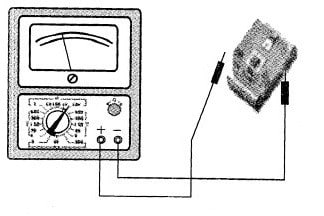
Figure 3
In Figure 3, the multimeter is set to “10 kΩ” gear (the cut-in voltage of the light-emitting SMD diode is 2V, so it can only be turned on when it’s in the “10kΩ” gear). Connect the red and black test leads of the multimeter respectively to the two outgoing lines of the light-emitting SMD diodes and then perform several measurements. When the pointer of the multimeter deflects to the right over half, and the tube shimmers a little, the black test lead is connected to the positive pole and the red test lead is connected to the negative pole of the light-emitting SMD diode.