Designing and building a coffee table
Follow article
 Dave from DesignSpark
How do you feel about this article? Help us to provide better content for you.
Dave from DesignSpark
Thank you! Your feedback has been received.
Dave from DesignSpark
There was a problem submitting your feedback, please try again later.
Dave from DesignSpark
What do you think of this article?

For a number of years, my colleague Andrew has had an old IBM mainframe CPU kept in storage, waiting to be transformed into something new. Hailing from a long-lost era of computing (the system in which this module was used was the 4381, first announced in 1983) – this is a far cry from what we might think of as a CPU today. It weighs approximately 20-30kg, and measures around 700mm x 650mm x 130mm!
With such size and mass, we decided that this CPU would make a great basis for a coffee table, with a glass top showing off the pleasant, intricate details of the hardware. In this post we will use DesignSpark Mechanical (herein referred to as DSM) – a free to use, powerful CAD software from RS – to design the table, before going on to build the table.
Planning the build

From the start, I planned to use Rexroth aluminium extrusion for the frame of the coffee table. Available in a variety of sizes, it is used for all sorts of projects, from desktop 3D printers and CNC mills, to partition walls and display stands.
Sitting down with a pad of paper and pen, I sketched out a few rough ideas for the structure of the frame. I find this a great way to start the conceptual phase before reaching for a computer.
Once I had a rough sketch on paper, I measured the CPU, with the intention of drawing a simplified 3D model of it, including any important features. For example, there are already threaded mounting holes on the body of the CPU, which I will make use of to affix it to the aluminium frame.
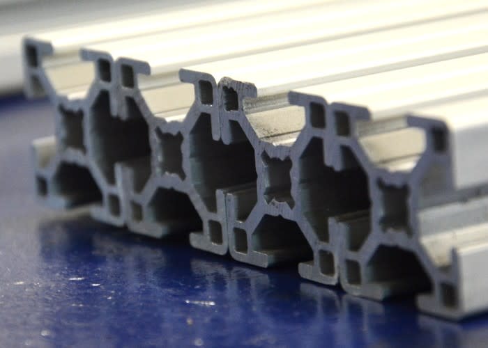
When it came to selecting the Rexroth profile, I settled upon the ‘30 Series’ profile: 30mm x 30mm cross section with 8mm slots. According to the manufacturer, suitable applications for this size profile include ‘medium-stress construction’, partitions and shelves. I had also considered the smaller ‘20 Series’ profile with 20 x 20mm section, but in the end felt that wouldn’t be quite up to the job.
Besides, we wouldn’t want to risk spilling our hot beverages should the smaller extrusion fail!
More sketching in DSM
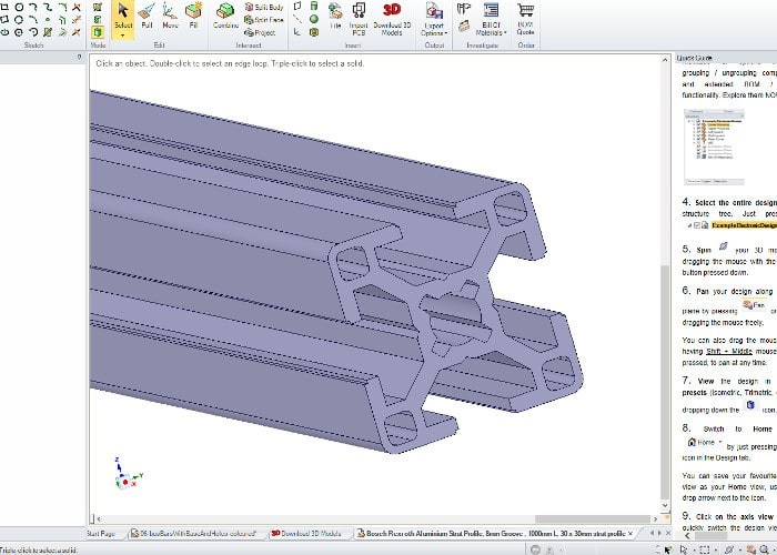
One of the handy aspects of DSM is the ability to import models directly from the RS catalogue, saving time in modelling the parts from scratch. Navigating to the product page (389-9796) for the extrusion, I was able to download the 3D model and import it into my design, alongside the simplified CPU model.
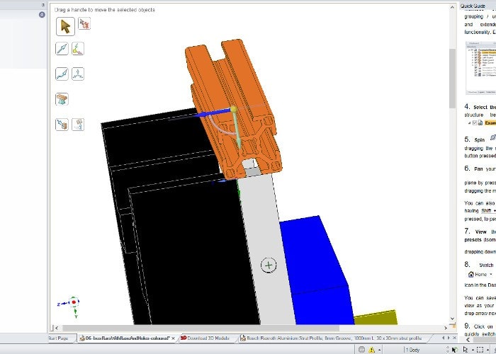
I then began to arrange copies of the extrusion model around the CPU, with my rough hand drawn sketch for guidance. I soon came to a point where I needed to include another modelled part – an angle bracket, to connect two lengths of extrusion together perpendicular to one another.

There is a huge range of accessories and connectors for use with this type of aluminium extrusion, including hinges, cable guides/clamps, end caps, mounting plates and brackets and so on. I used two different angle brackets for this design, along with several end caps, to give a neat finish to any exposed cut ends of extrusion.

It turned out that the bracket I chose did not have a 3D model available through the RS website at the time of writing (though the range is being extended as we speak). However, I was able to visit the manufacturer’s own website, and download a 3D model file from there.
I was then able to import this file into DSM and use it in the design as required.
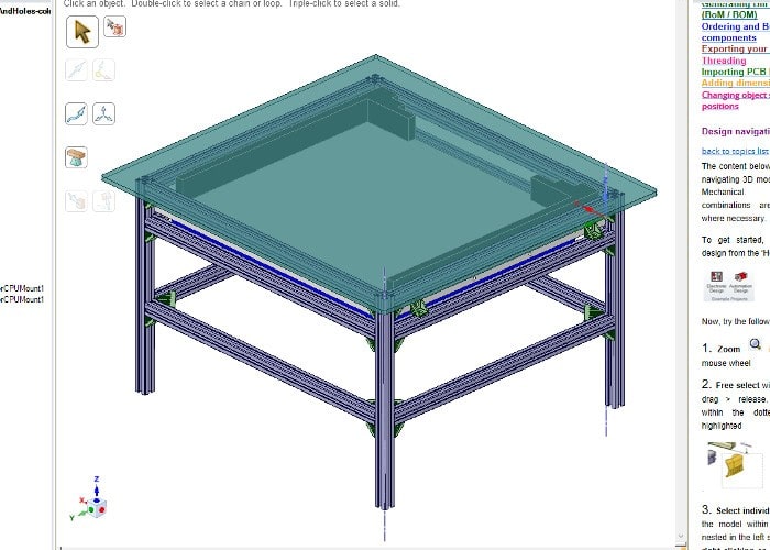
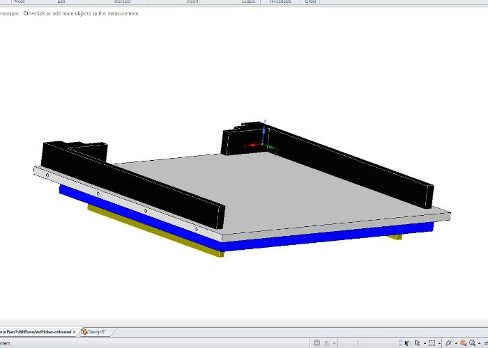
By using these models along with my own simplified CPU model, I was able to quickly draw and visualise the coffee table, determine just how many angle brackets were needed and what lengths of extrusion would need to be cut.
I then added a top surface to the model, modifying the appearance to be translucent, to visualise and thus decide upon the size of the glass top of the table.
Once I was happy with the drawing, I saved the file and did the following:
- Used the ‘Measure’ tool to make a note of each aluminium extrusion length
- Calculated how many lengths of extrusion were required
- Counted the number of angled brackets required
- Made a note of the glass top dimensions, again using the ‘Measure’ tool
- Took screenshots of front, side and isometric views, to print out and refer to when building the table
The build

Once the extrusion and other parts were delivered, I measured out and cut the extrusion into lengths using a horizontal bandsaw. Care was taken to ensure that each length was correct within +/-0.5mm, and I used some pieces of MDF as ‘soft jaws’ for the vice, to reduce the likelihood of damaging the relatively soft aluminium.

This bandsaw was the best tool we had for the task, though the ends did require some finishing by hand, to remove any burrs or sharp edges. I have since purchased a small chop saw that gives a better finish that does not require any finishing.

Building the frame was then a simple task of using the angular connectors along with the supplied cap head bolts and special ‘T nuts’ that fit into the slots that run the length of the extrusion. The frame took shape very quickly and felt incredibly sturdy, it was a real delight to assemble!

I had planned on using 4 of the angular brackets to attach the CPU to the frame, which required a little modification. Firstly, I needed to remove two tabs from each connector. These tabs are intended keep the connectors square on to the extrusion, as they fit into the slots nicely. They are also designed to be easily snapped off to allow for alternative orientation.

Since the CPU has M8 mounting threads in the side and I did not wish to drill the CPU itself if it could be avoided, I instead drilled 8mm holes in the 6mm slots in the brackets. By holding each bracket in a drill press vice, I was able to do so with suitable precision, preventing the drill or bracket from wandering.

I used a slightly larger angular bracket in each corner of the table frame, to improve rigidity and reduce the likelihood of twisting or warping. I only used four, as they were quite a bit more expensive than the smaller brackets and seemed a bit overkill for this application.

Before I knew it, I had the CPU mounted within the frame and the end caps added to the top and bottom of each leg, the only exposed ends in the build. I was pleased with how quickly and easily the table came together, and how strong and rigid it is!
Now I just had to wait for the glass to arrive from the fabricators, and the table would be complete.
Final thoughts

DesignSpark Mechanical proved invaluable in drawing up the design and specifying which parts were required for this project, saving time in the design phase, as well as the build. The ability to import existing models is great, as it saves time and provides known dimensions and features from which to work.

Without first modelling the table in CAD, it is likely we would have had to order more extrusion than required, incurring more expense, and would not have had the confidence to cut up all of the lengths before assembly, taking more time over the construction.
All in all, it was a satisfying build, and I look forward to making more projects from this and other size extrusion. Last but not least, the CPU that has been stored and looked after for a rather long time has now been put to good use, as a feature coffee table for our workshop!