Creating a moisture sensor with Raspberry Pi
Follow article
 Dave from DesignSpark
How do you feel about this article? Help us to provide better content for you.
Dave from DesignSpark
Thank you! Your feedback has been received.
Dave from DesignSpark
There was a problem submitting your feedback, please try again later.
Dave from DesignSpark
What do you think of this article?
Utilizing a Single transistor circuit to create a moisture sensor.
The Problem.
In my last post, I wrote about getting to grips with using the GPIOs on a Raspberry Pi to interface hardware, and how I wanted to use this knowledge to create a moisture sensor that would monitor bed bound patients on NHS wards to improve patient health and dignity.
Currently the target on Bradford Teaching Hospitals NHS Foundation Trust wards is to check the bedsheets of bed bound patients every 4 hours. This means that a patient could be checked at 9am, wet the bed at 9:15 and in theory remain in a wet bed for the next 3 hours and 45 minutes.
This is a blow to their dignity and a poses a great risk to their health. Wet skin is more susceptible to breakage and pressure sores than dry skin and can impact the cost of care astronomically. The daily costs of treating a pressure ulcer per patient are estimated to range from £43 to £374. For ulcers without complications the daily cost ranges from between £43 to £57 (Bennett, Dealey and Posnett, 2012). The average length of stay for in inpatient across Great British health care trusts is 5.6 days (Health and Social Care Information Centre, 2013), and hospital-acquired pressure ulcers increase the length of stay by an average of 5–8 days per pressure ulcer (Bennett, Dealey and Posnett, 2012). Therefore, costing a minimum of £215(£43 x 5 days) for a simple case, to a maximum of £2992(£374 x 8 days) for those involving more complications.
Surely simple electronics can be incorporated into daily use on wards to tackle this problem?
The solution.
A simple moisture sensor circuit made of a single transistor and a few resistors, and a Raspberry Pi.
I wanted to use as few components as possible. The less components I use, the less it costs to manufacture and maintain, and the more likely it is to be implemented.
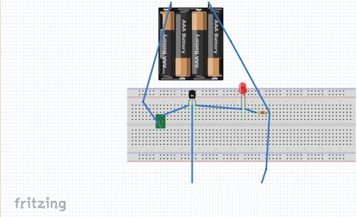
The moisture sensor circuit I settled on can be seen below in the schematic and breadboard diagrams I created using Fritzing.
The circuit
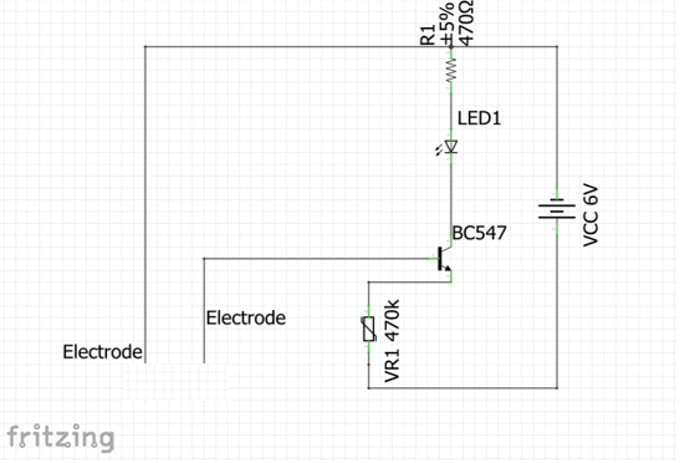
It’s a simple circuit that works on the basis that in air, the resistance between the electrodes is too high to conduct electricity and form a complete circuit that will turn on the LED.
When the electrodes are placed in water — or in the case of our target liquid, the presence of sodium, potassium, creatinine and other charged ions — this will allow for the completion of the circuit, a current to flow and the LED to be turned on.
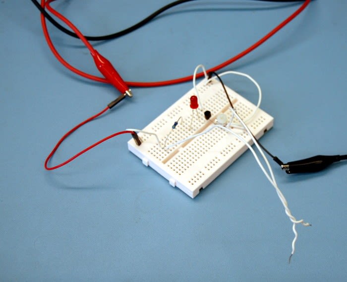
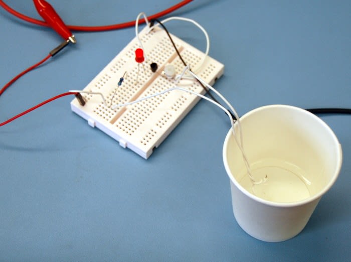
This victory can be seen in the picture below.
Now I know my circuitry is sound, the next step is to ditch the LED and get the Pi involved.
The software
My ultimate target was to have the computer display a help indicator located on a nurses station, either through lighting up an LED next to a bed number or sending a message on a screen. Since I controlled LEDs in my last post I chose to challenge myself to explore Python a little further and print a help message.
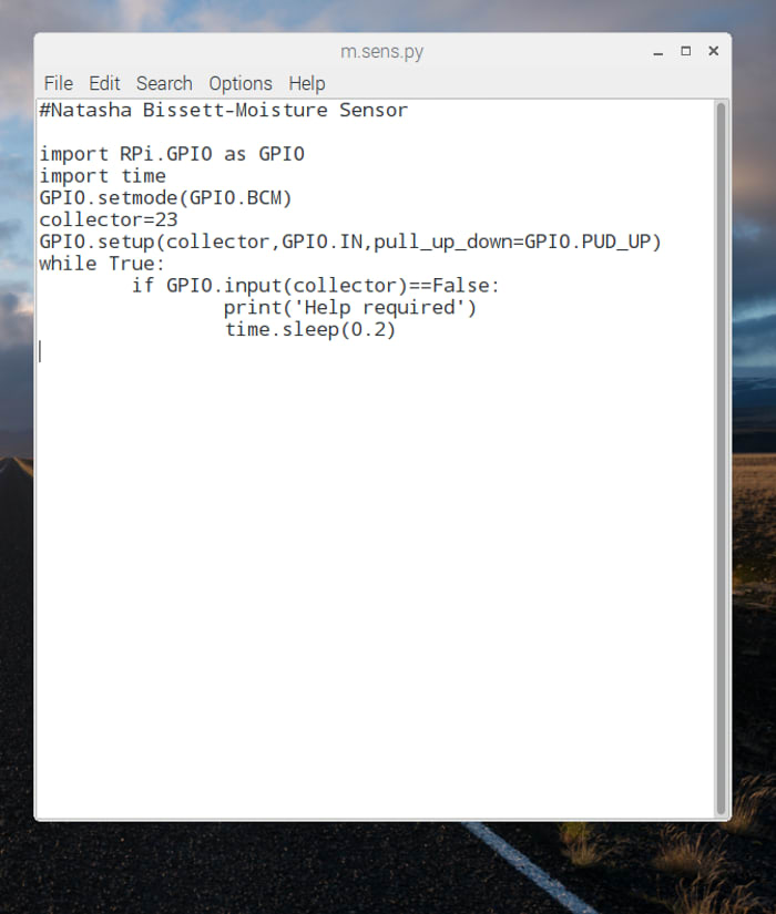
To do this I opened my text editor and imported both the GPIO and time library as I would need both. I instructed the Pi I wanted to use names of the GPIO pins rather than numbers using the line GPIO.setmode(GPIO.BCM) BCAM, and defining via a variable that Pin 23 is the is the collector using collector=23. GPIO.setup(collector, GPIO.IN, pull_up_down=GPIO.PUD_UP) facilitates an internal pull-up resistor on pin 23 to keep the input on logic level 1(True) unless it is connected to ground, which will happen if the electrodes are placed in water, and when this happens it will override this, pull the logic level to O(False) and then print out the line ‘help required’. This is defined in the last lines of the code. The time.sleep(0.2) instructs the Pi to re-evaluate the status of the circuit every 0.2 seconds. In the real world this would not be necessary, we would set it to re-evaluate and send another help indicator every 5 minutes or so, but for this test it was a good way of showing us that the circuit was staying in its loop and working correctly.
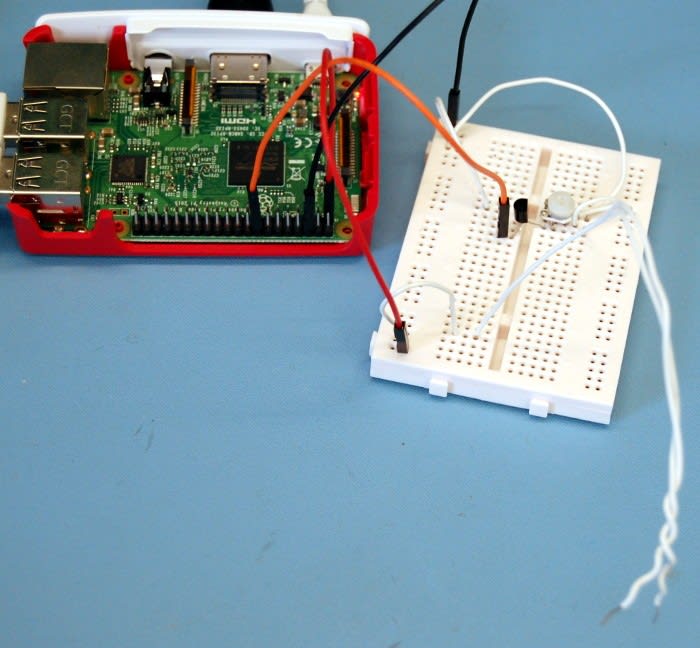
Now I’d reached the crunch point. Time to hook up my circuit to GPIO pin 23 and to the GND pin on the pie as seen below and get to testing.

I placed the electrodes in the water and crossed my fingers that the help line would be displayed.
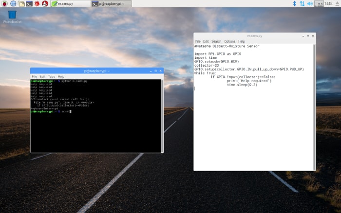
Success!!!!! This can been seen working in the video too.
The next step.
Now I know I have a successful moisture sensor, my next challenge is to make it a bit more user friendly. Nobody wants to sit on bare wires all day. The plan is to use a conductive thread in place of my wire electrodes and sew them into a cotton square for prototype development and consider ways of programming my pie to display the help needed on a nurse’s station and keep a log of the information it is recording to be placed into tracking graphs and compiling the kind of data that will allow for target setting and save a lot of man hours in the long run. Stay tuned.