Constructing a High Current 28V DC Power Supply
Follow article
 Dave from DesignSpark
How do you feel about this article? Help us to provide better content for you.
Dave from DesignSpark
Thank you! Your feedback has been received.
Dave from DesignSpark
There was a problem submitting your feedback, please try again later.
Dave from DesignSpark
What do you think of this article?

This post takes a look at assembling a high current DC power supply that is rated at over 60A, for use with military surplus and other electronics which would typically be vehicle-powered.
A colleague is currently in the process of building a control system for an aircraft rotary inverter, which takes a 28VDC power supply and generates a 3-phase 115V 400Hz output (you can follow his progress so far in Part 1 and Part 2 blog posts). One challenge with this is that the inverter will draw around 44A at 28V, hence a rather substantial DC power supply is going to be needed! This post takes a look at assembling a high current DC power supply that is rated at over 60A, for use with military surplus and other electronics which would typically be vehicle-powered.
Fortunately, we just happened to have two surplus to requirements TDK-Lambda SWS1000L-24 (680-2852) switch-mode power supplies, which can be set for between 19.2-28.8V output and may be wired in parallel. With a maximum power rating of 1056W each, and a total in parallel configuration of this multiplied by two and then 0.9, this should be plenty for the intended use.
SWS600/SWS1000L series
The TDK-Lambda SWS600/SWS1000L series power supplies boast features that include:
- Low Profile
- Active Power Factor Correction
- Universal Input (85 - 265VAC)
- Input Transient Protected IEC61000-4
- Low Acoustical noise
- Medical Certifications (SWS1000L)
Available in 3.3V, 5V, 12V, 15V, 24V, 36V, 48V and 60V models, with the SWS600L versions rated at ~600W and the SWS1000L versions rated at ~1000W output — apart from the 3.3V models which are rated 396W and 660W respectively.
Handily for us, up to 5 power supplies may be wired in parallel for increased current output. They may also be connected for series operation and additional features include over-voltage, current and temperature protection, along with remote sensing and on/off control, plus alarm signal output.
System features
The intention was to create a solution that would ultimately be safe, practical and robust — a useful addition to our lab equipment collection. It was decided to house the power supply in a 19” rack mount enclosure and for this, we selected a 3U 460mm deep MultipacPRO enclosure from Schroff (2550487120), with the optional chassis plate (721-2935) for securing the main components to. The other key features that were decided upon are:
- Output voltage and current metering
- Circuit breaker for output protection
- Output on/off switch (in addition to mains input switch)
- 4x high current outputs via MIL standard connectors
- Additional EMC filtering on the input
This last point was thought to be an advisable precaution since we may be driving some electrically noisy loads, such as a vintage 400Hz rotary inverter!
Assembly

I should note that my colleague, Dave Ives, was responsible for the metalwork and here I’ll give a summary of the steps taken in preparing the enclosure.

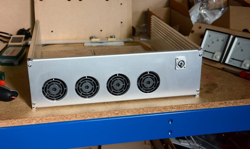
First of all the enclosure was assembled, complete with the chassis plate. Following which the internal components were located on the chassis plate and a front panel was prototyped from laser cut MDF. As can be seen above, the power supplies and substantial DIN rail terminals take up most of the space, so a custom mounting bracket had to be fabricated for a 100A MCB (043-5352) and a 100A plate shunt (392-8399) for the panel meter. The bracket was laser cut from 5mm acrylic and has slots etched into either end, which line-up with the rails in the enclosure side panels.

Once the panel layouts were decided upon, the smaller holes could be drilled.
The larger circular holes needed to be cut with a hydraulic punch.

Unfortunately, we don’t have any square punches and so the two cut-outs for the panel meters were chain drilled and filed, during which the aluminium was securely clamped between two laser cut MDF templates to act as a guide. A pretty time-consuming task.

2-pole circular military spec connectors that are rated at 80A were used for the four outputs.
Current balancing
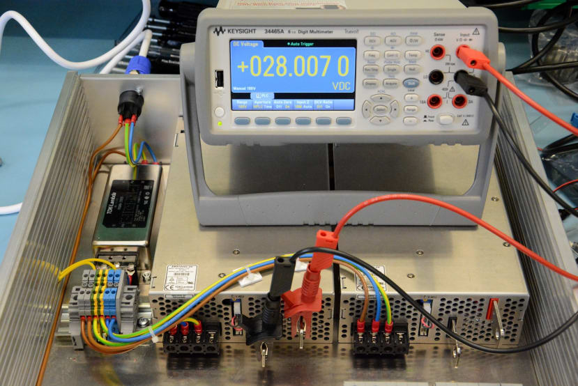
The power supplies have a current balancing feature that is enabled by wiring the PC and COM pins of the JST connectors, between power supplies. However, it is also important to first adjust the voltage output of each power supply to be as close as possible, so that one doesn’t end up doing more work than the other.
Cabling

The power supply output was cabled in 16mm2 red (516-8038) and black (516-8016) cable. The positive terminals of each PSU were joined at the 100A shunt, while the negatives were combined at suitably rated DIN rail terminals.
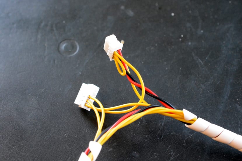
A cable harness was made up with four JST connectors — two for each PSU — and that also connected to the DPST front panel switch that enables the output, plus two red indicators (666-7334) for the PSU alarms. The PSUs also feature a 12V/0.1A axillary supply that is always-on, which was used to power the two indicators, since the alarm outputs are open collector. These are only specified to sink up to 10mA, so a resistor was selected to limit the current to just under.

Dymo heat shrink tube (515-6798) was used to label the wires at the switch/indicator ends.
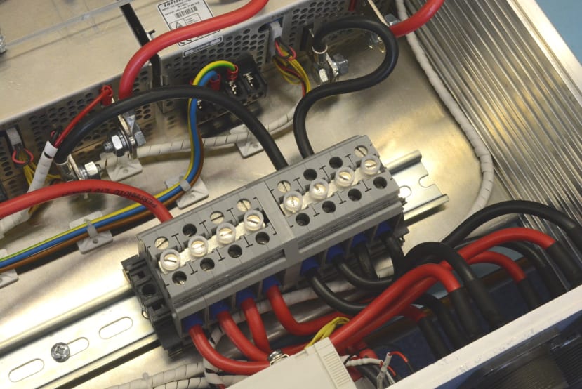
It’s surprising how little space is left after cabling and particularly when 16mm2 cable is involved. Note also how the cables from each power supply had to be kept the same length, so as to ensure that the resistance is closely matched, which resulted in some cable length having to be lost in a wiggly section.
Testing
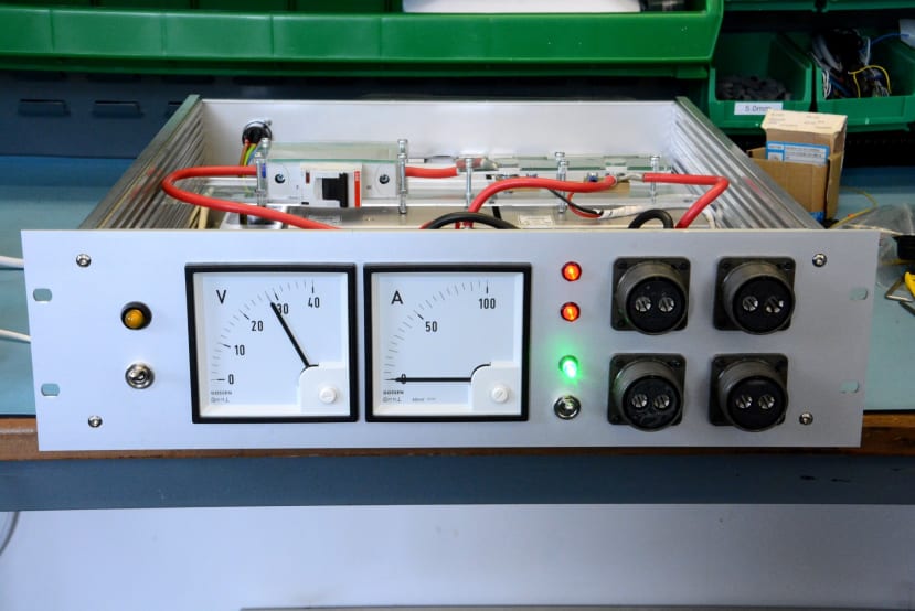
Upon powering up everything seemed to work as expected, with the exception of the two-alarm indicators, which were illuminated when it was thought they shouldn’t be. However, the PSUs fans were running and output was enabled, so we quickly came to the conclusion that the alarm output must be inverted. One option would be to change the two red indicators for green, so instead these more obviously indicate “PSU OK”.
Wrapping up
Finally, the top and bottom ventilated covers were fitted, along with the optional front handles (469-1307) . The end result is particularly neat and we’re pleased with how this project has turned out. Which is good news considering that it turned out to be somewhat more of a time-consuming build than originally expected, but at least now we should have a fairly capable PSU for future projects.