Catching a Bus: Basic Serial Communication Part 1, the UART
Follow article
 Dave from DesignSpark
How do you feel about this article? Help us to provide better content for you.
Dave from DesignSpark
Thank you! Your feedback has been received.
Dave from DesignSpark
There was a problem submitting your feedback, please try again later.
Dave from DesignSpark
What do you think of this article?
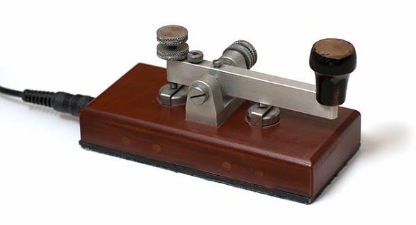
Image credit: Simon A. Eugster
Most modern peripheral device chips, such as sensors and motor drivers, communicate with a controller via a serial data bus. Microcontrollers usually support one or more of three basic types: UART, SPI and I2C. How do they work and which to choose?
Early Telegraphy
In the days before voice could be converted to an (analogue) electrical signal and conveyed over long distances by wire, there was digital telegraphy. Well, sort of. A human operator sent text characters encoded in groups of short and long current pulses (dots and dashes) by tapping a sprung-loaded switch known as a Morse key. At the receiving end, a solenoid-driven ink stylus reproduced these ‘marks and spaces’ on paper tape fed from a roll by a clockwork motor. Alternatively, the ticks and tocks of the solenoid could be interpreted directly by a trained Morse code telegraphist. I won’t cover the very similar ‘Ticker-tape’ systems designed for stock market price communication as these are now well and truly obsolete.
Keyboards and printers
Sending and reading messages in Morse code was never going to catch on as a means of mass communication because it’s too slow and requires a trained operator at each end. Though when combined with long-range HF radio, it’s great for sending three-character messages like “SOS” from ships in distress. What was needed was a means of replacing the Morse keys with office typewriter keyboards. A way had to be found for converting a key press to a coded stream of electrical pulses, which could then be decoded and converted to a character printed on paper at the receiving end. All this had to be achieved with the only technology available at the time: mechanical mechanisms driven by electric motors and solenoids. No electronics. The electromechanical Asynchronous Receiver Transmitter was born.
Asynchronous communication and the UART
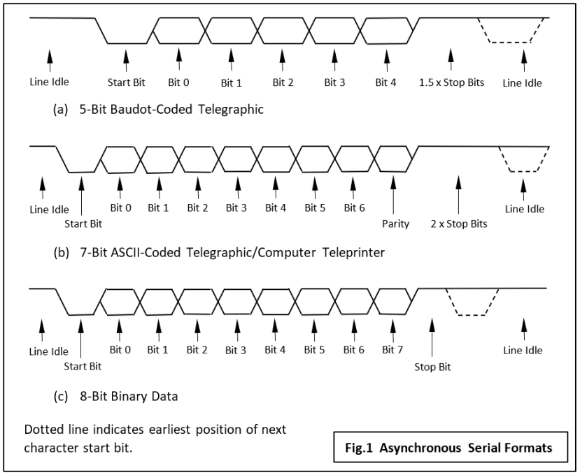
To make life easier, each character is represented by a fixed-length 5-bit binary code (unlike Morse) and the distinction between ‘zeros’ and ‘ones’ based on voltage or current level, not pulse length (Fig.1). For signalling purposes each character is preceded by a Start bit - always a zero, and ends with a Stop bit (always a one). The signal line is held in the ‘one’ state when nothing is being transmitted.
One feature of all types of digital communication system is that the clock signal which puts the data on the line, in the serial case one bit at a time, is precisely synchronised with the receiver’s clock taking it off. This can be achieved in one of two ways:
- The transmitter clock is supplied to the receiver via another wire.
- The receiver ‘recovers’ the clock from the data signal itself.
The first method is used over short distances where there is no problem providing an extra wire. For example, when linking a peripheral device to a microcontroller on the same PCB. The SPI bus which I’ll talk about next time is frequently used in this situation.
The second approach is invariably used in wireless systems to avoid dedicating a separate frequency channel to the clock signal. It was also required in early telegraphic systems which used existing long-distance cables where adding extra wires would have been prohibitively expensive. Sending digital messages between two devices that don’t share the same clock signal is called Asynchronous communication and the peripheral interface hardware present in most microcontrollers is the Universal Asynchronous Receiver-Transmitter or UART (pronounced ‘you-art’ for short).
The (Non-)Standard Asynchronous Serial Bus
At this point I have to say that there is no complete ‘standard’ for this type of serial digital communication. The earliest, and now obsolete signalling format is shown in Fig.1a, based on the 5-bit Baudot code (plus a number of variants). In the 1960’s a 7-bit code was devised – American Standard Code for Information Interchange or ASCII code. Although developed for telegraphic use, it quickly became the standard for textual data stored on computers and has been ever since. Fig.1b shows the similarity in signal format between an ASCII character and its 5-bit predecessor. The addition of an optional Parity bit for the purpose of error checking brings the total number of bits per character to eight – plus the start and stop bits. The format shown in Fig.1c is very commonly used nowadays for short links between microcontroller chips and peripheral devices often mounted on the same board. The parity bit is replaced by a further data bit so a complete byte of binary data, i.e. not necessarily ASCII-coded text may be transmitted.
Start and Stop
So, what function do the Start and Stop bits have – apart from marking the beginning and end of a short stream of data bits? As I mentioned above, the early teleprinters contained no electronics so the signal format was developed based on the limitations of electromechanics. Somewhat simplified, this is how a stream of electrical pulses were converted to a character printed on a roll of paper:
- The leading (falling) edge of the Start bit causes the wiper arm of a five-contact rotary switch driven by an electric motor to begin moving. Its speed is matched to the data rate.
- The incoming signal line is ‘sampled’ as the wiper crosses the first contact and the value of bit 0 recorded as the position, up or down of a metal pin. The other four bits are recorded in turn on other pins as the wiper rotates.
- After this ‘serial to parallel conversion’ has taken place, a mechanical ‘decoder’ causes an incredibly complicated series of levers and cranks to rotate and lift the print head into the correct position, before bashing it through an inked ribbon onto the paper.
- The Stop bits represent the minimum time that must pass before the Start bit of another character may be accepted. Hence the ‘one and a half’ bits for 5-bit machines and two for ASCII-based printers. Of course, an electronic UART doesn't really need anywhere near even a 1-bit interval.
Note how synchronisation of transmitter and distant receiver is achieved at the character level when the Start bit triggers the mechanism. The system assumes that the motors (‘clocks’) at each end are governed to run at approximately the same speed. The long bit intervals resulting from a low baud rate means that the receiver timing will not have drifted far enough to cause an error by the time the Stop bit arrives. The same principle applies when using electronic circuits, except that tighter tolerances on the clock signals mean that maximum baud rates are higher.
UART Communication today
Those old teleprinters of the past were fantastic examples of precision mechanical engineering, but electronics and the ‘glass terminal’ (CRT display and keyboard) have swept them all away. All except the signalling format that is. One of the first large-scale integrated (LSI) chips produced in the 1970’s was for an electronic UART. At its heart the device consists of two shift registers: a parallel-in serial-out type for transmission and a serial-in parallel-out for reception. To cater for all the variations in format in use at the time, even these early devices could be programmed for character length, number of stop bits and selection of even, odd or no parity. The data or baud rate was set by an external oscillator connected to a device pin. The receiver and transmitter were completely independent and could even operate with different baud rates! Hence the ‘standard’ rate available of 75 baud for the relatively slow humans typing on the keyboard and 1200 for the electronic display unit. For modern inter-chip communication you’re unlikely to use less than 9600 baud. This programmability of the serial interface for different signal formats explains the ‘U’ for Universal in the term UART. Stand-alone UART chips still are available, but just about every modern microcontroller chip has at least one built-in.
The RS-232 standard
Now we come to one of the most mis-used terms in electronic communications: RS-232. You will frequently find chip or module manufacturers claim on their datasheets that the UART channel on their device conforms to it. It rarely does. The international standard RS-232 defines the electrical characteristics of the serial link such as signalling voltage, line impedance and the functionality of all the 25 signals (!) that could be used in a full implementation. It does not specify data formats, baud rates, error protocols or a maximum cable length. On chips with an integral UART you will usually find the two serial I/O pins marked as Tx and Rx, sometimes accompanied by ‘handshaking’ pins RTS and CTS. These operate with normal logic-level voltages and not the higher bipolar voltages specified by the RS-232 standard. The standard applies to low-speed serial cable links (up to about 20 kBaud) between pieces of equipment no more than a few metres apart.
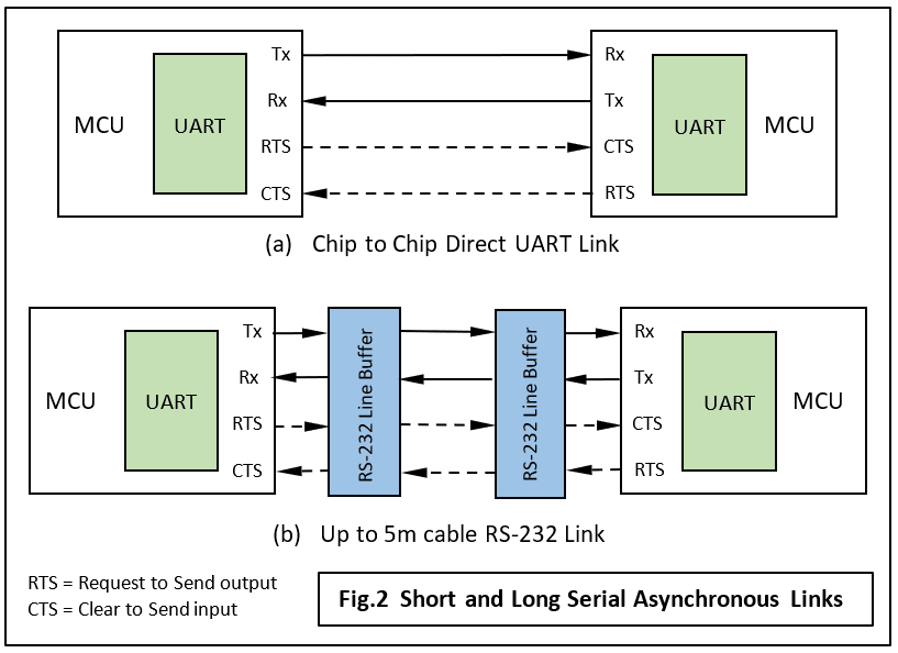
Most likely your connection will only be few centimetres long, so no other interface circuits are required (Fig.2a). On the other hand, if a project involves a serial connection to a PC via its 9-pin COM socket for example, then an RS-232 interface chip (Fig.2b) will be needed to convert your board's UART logic-level voltage to the PC's bipolar signalling level of around ±12 volts. PC COM ports will often work with just the logic voltage – but this falls into the category of ‘Things-You-Might-Get-Away-With’ and is not recommended.
Handshaking
A big disadvantage with a transmitter operating independently of the receiver is that it can just begin sending data even if the receiving device is not ready for it. With a low baud rate and at least one buffer register at each end, this kind of operation is practical. It’s called ‘double-buffering’ on a UART datasheet, and hence a simple bi-directional asynchronous link may only need three wires for Tx, Rx and Ground. At high data rates, two ‘handshaking’ signals defined in the RS-232 standard, usually Request to Send (RTS) output and Clear to Send (CTS) input will be required to provide ‘Flow Control’. These are shown as dotted lines in Fig.2.
Driver code for an MCU UART
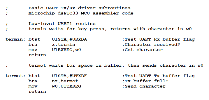
Here is a code fragment for basic UART I/O functions on a Microchip dSPIC33 DSC chip. The initial setting up routine is not shown, but you can see how the attachment of Start/Stop bits, etc. to the data byte is all handled by the hardware making the driver routines very small indeed.
Finally
This form of serial communication has been superceded long ago by newer, faster technologies such as SPI, I2C and USB. But it still hangs on as a simple to implement solution where speed is not an issue and all you need is a one-to-one, non-networked connection.
For those interested in electromechanical communication, here is a glimpse of the past showing how a teleprinter’s Baud Rate Generator frequency was adjusted….
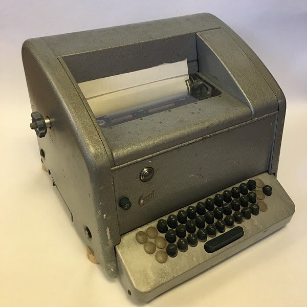
A somewhat scruffy but otherwise in full working order Creed 75 teleprinter of about 1960 vintage. Capable of printing 10 characters per second from a 75 baud asynchronous serial link. Originally designed for telegraphy work, they were frequently used as keyboard terminals on British computers of the time.
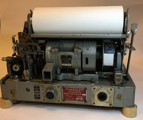
Rear view with the casing removed. The motor underneath the paper roll governed the signal timing and provided the force to move the huge number of levers and cranks making up the mechanical ‘logic’ system. The speed governor is in that drum with the white patch on the right-hand motor shaft. It’s a simple spring-loaded switch that opens when the rotational speed exceeds the set value.
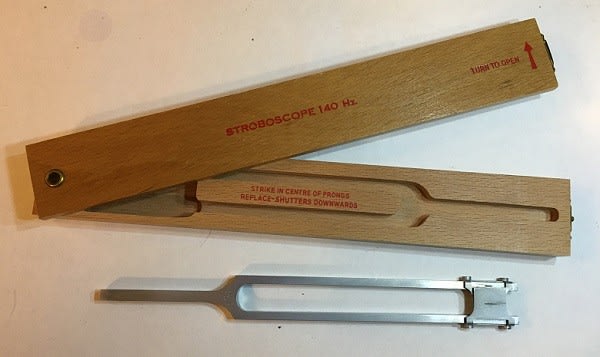
Baud rate timing adjustment – electromechanical style. This special tool is a tuning fork with a shutter on the end which opens and closes at fixed frequency when the fork is struck.
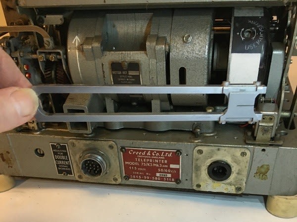
The vibrating fork is held in front of the rotating governor and the white bands observed through the shutter. This is a mechanical stroboscope and the drum will appear stationary if the speed is correct. If not, then an adjustment is made to the screw in the black band on the drum.
More Content in this series
Serial Peripheral Interface (SPI)
Prototyping a wireless robot control box
If you're stuck for something to do, follow my posts on Twitter. I link to interesting articles on new electronics and related technologies, retweeting posts I spot about robots, space exploration and other issues.