Building a Rotary Inverter Controller with a Barth lococube mini-PLC Part 1: The Controls
Follow article
 Dave from DesignSpark
How do you feel about this article? Help us to provide better content for you.
Dave from DesignSpark
Thank you! Your feedback has been received.
Dave from DesignSpark
There was a problem submitting your feedback, please try again later.
Dave from DesignSpark
What do you think of this article?
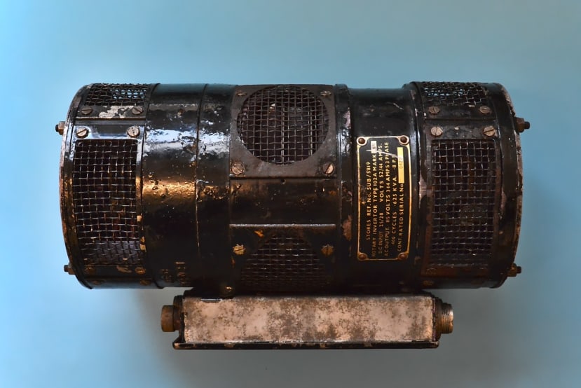
Building a control system for a vintage aircraft 400Hz rotary inverter.
For some of our future planned projects, we have a need for a three-phase, 115Vac 400Hz power supply - the same as can be found onboard aircraft. Whilst we could attempt to build a solid-state inverter to generate this supply, we ended up acquiring a vintage rotary inverter that would be rather more fun to get up and running.
Controlling the Inverter
The rotary inverter can be viewed as a motor-generator set, with an armature and field coil on the motor side, and then a field coil on the generator side that will also need to be controlled. Adjusting the motor field current will control the output frequency, and adjusting the generator field current will control the output voltage.
To close the control loop, we will be using two of the BARTH lococube mini-PLC STG-820 (134-8867) , which are inexpensive yet surprisingly powerful PLC type controllers. The BARTH website describes this as being a “CAN Logic Controller''. It features a CAN interface, three 0-30Vdc analogue inputs, two digital inputs, one 0-5Vdc analogue output, and four digital outputs.
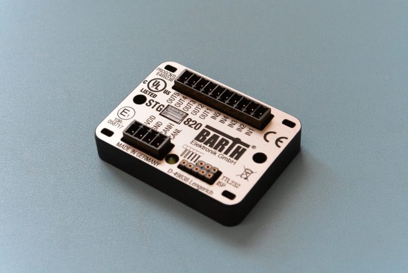
In addition, the PLC can either be programmed using a block-based programming language called miCon-L that is provided by BARTH, C/C++ using the KEIL MDK or STM CubeIDE, or even the Arduino programming environment. All three programming methods are easy to use, with good supporting documentation provided.
We will be using two of the controllers as we need two analogue outputs, and each controller only supports one analogue output. However, this also allows us to neatly split the configuration and associated logic into two halves, for motor and generator.
As we need to measure some rather funky voltages and frequencies, we are using the Trumeter APM-FREQ-ANO (815-8330) for frequency, and the Trumeter APM-VOLT-ANO (815-8306) for voltage. Both these meters offer 4-20mA current loop outputs, will then be fed into a current-to-voltage converter module.
The PLC can then control the field currents through the use of a simple voltage to high-side current converter. This is taken from a Texas Instruments Precision Designs document (SLAU502) and requires a dual, or two separate operational amplifiers, two MOSFETs and a sprinkling of passives.

Getting Started with the lococube mini-PLC
The BARTH lococube STG-820 PLC is easy to get up and running with, needing only the VK-16 serial programming cable provided by BARTH. An alternative programming method — if using KEIL/STM CubeIDE, or the Arduino environment — is to buy the VK-35 cable and an ST-Link or other SWD (Serial Wire Debug) capable programmer. This allows for programming at a lower level using C/C++.
We will be using the miCon-L programming language in this project, as it provides a drag-and-drop visual environment which means programs are quick to assemble and easy to debug, as once uploaded to the PLC the program operation can be observed in real-time.
To get started, we downloaded the miCon-L application, and extracted it to a folder. It is worth noting that the installer is actually a self-extracting archive, and needs to be extracted to somewhere other than the default location of “C:\Windows\system32”.
Once extracted to a folder, there is a PDF that is a “Getting Started” guide, and then the programming environment itself. The programming environment launches to a selection window with a start button, amongst others.
In this sample program, we will limit the range of analogue input and mirror that to the 0-5Vdc analogue output.

We started by creating a new project, with the appropriate PLC type selected - the STG-820. Once the project has been created, we are presented with a default project containing an LED blinker that toggles the status indicator.

To get started, we dragged in the “Analog Input” IO block, which outputs a float value representing the 0-30Vdc input range of the controller. The user interface has a slightly peculiar feel, as instead of dragging the “Analog Input” item onto the programming area, you drag the block representation above it.
As we want to limit the range of the input to the range of the output, which is 0-5Vdc, we drag a “limiter” block onto the diagram and connect the input to the output of the analogue input block. This is as easy as clicking on the output node of the block, and clicking on the input of the next block - the connection is automatically made. With the limiter now placed, we can set the minimum and maximum values to limit to — this is done by looking at the documentation for the block, right-clicking on the min/max pins and assigning a parameter. Parameter assignment is documented here and is well worth reading to familiarise yourself.

With the input now limited, we can add the analogue output block, and connect the limiter output to the block. This means that we should now be able to mirror 0-5Vdc on the analogue input to 0-5Vdc on the analogue output. We can add a numeric visualisation to the input and output connections so that when we run the simulation we can observe the changes.
Macroblocks can also be created in miCon-L, which helps to make programs neater and more modular. As our meters output 4-20mA, we have two current-to-voltage converters that provide 0-10V output, which then needs converting into a voltage and frequency again.

To do this, we created a Macro Block called “V-TO-F” that contains the logic and maths that converts 0-10V into 0-400Hz. This block contains a limiter (as dividing a 0V input by zero would not compute) to limit the input range from a very small positive value to 10V, and then a “F-GEN” block to hold the equation to convert to frequency.
To begin the simulation, we head to the “Run” menu then click “Simulate” which compiles the program and runs it on a virtual PLC. The view then switches to the simulation environment, and shortly afterwards we should see the status LED blinking. We can then manually input analogue values by right-clicking on wires connecting function blocks together.

As the program works in the simulation, we can now try it on the PLC. Our setup consists of a potentiometer connected to the PLC supply rails, and the wiper going into “IN1” — our chosen analogue input. The 0-5Vdc output is connected to a multimeter set to the volts DC range so we can monitor the output voltage.

Compiling and downloading the program can be done from the “Run” menu, by clicking “Download”, which downloads the program and puts the programming software into the observation mode.
By adjusting the potentiometer, we can see the real-time updates of the input voltage and the output voltage on the observation screen, and the 0-5Vdc output also changes to match the input.

Various graphing options can also be added to the PLC program so that the input and output values can be visualised easier. This is done by dragging and dropping a “Trend-Writer” block that can plot up to 4 values over time. We can now see a plot of changing the voltage in real-time.

Conclusion
In this article we’ve taken a look at the basics of the rotary inverter, and what we need to control to set the voltage and frequency output. We’ve also explored the BARTH lococube STG-820 mini-PLC, and some of the capabilities it has, and also how easy it is to get started with.
In part 2, we will build up the control system and enclosure for the rotary inverter, and apply some power to see how well the inverter works, then in part 3 we will finish the assembly and test the operation of the rotary inverter.