Building a Lyra-8 Synthesiser Part 2: Completing Assembly, Debugging and Designing a Case
Follow article
 Dave from DesignSpark
How do you feel about this article? Help us to provide better content for you.
Dave from DesignSpark
Thank you! Your feedback has been received.
Dave from DesignSpark
There was a problem submitting your feedback, please try again later.
Dave from DesignSpark
What do you think of this article?
Assembling the control and I/O boards, testing it and fabricating an enclosure.
In the first part of this series, I gave a bit of background on the Lyra-8 synthesiser and detailed how I assembled the components and put the mainboard together. Now it was time to tackle the two other PCBs – the control board that has all the knobs and switches and a smaller board that has all the inputs and outputs.
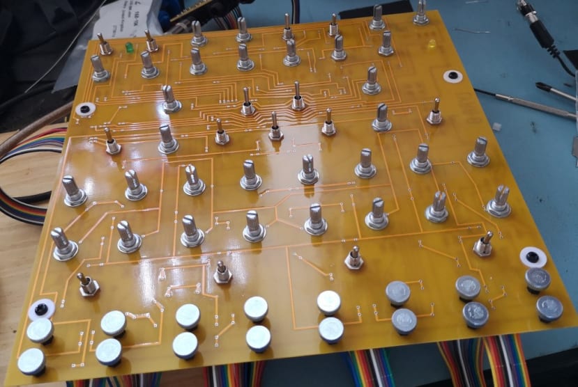
The control board PCB is slightly unusual in that it has SMD style solder pads, but takes through hole components. I am not quite sure why it is designed like this other than making it possible to mount it completely flush with the front panel and maybe to give the option of using potentiometers with different mounting types.
Soldering the Control PCB
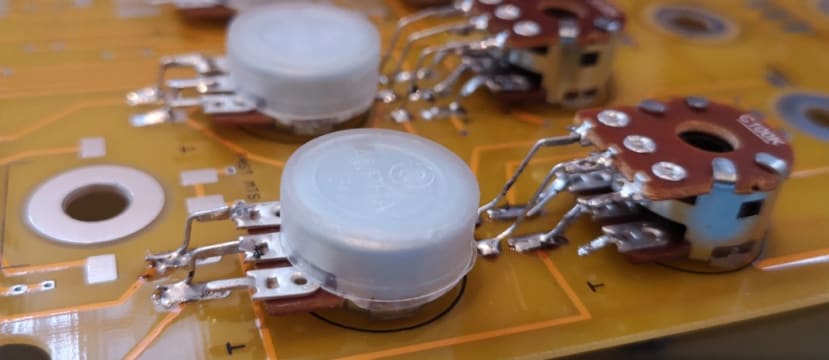
Because of the design of the PCB, each switch and potentiometer needed short wires soldering to its connectors.
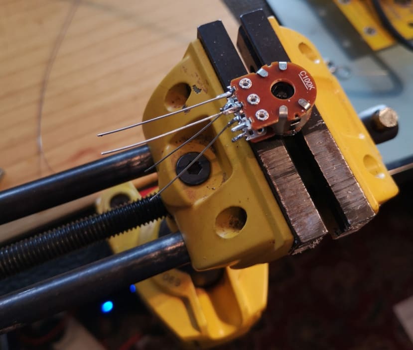
After some trial and error, I decided it was best to do this away from the PCB, holding the component in my handy Stanley Multi-Angle vice (667-7189) .
I then fitted the potentiometer or switch to the board with the appropriate nut, making sure it was firm enough not to move, but not so tight that it would be difficult to undo the nut later to fit the board to the front panel. I could then bend the wires so they contacted the correct pads and solder them in place. I had noted that I would need lots of short lengths of wire for this part, so had saved all the cut off bits from building the mainboard.
Some of the potentiometers needed 300 ohm (014-8376) resistors in place of the wire “legs” — this is clearly marked on the PCB itself.
The switches are labelled MTS-202, 203, 102 and 103, which I worked out meant:
- MTS-202 – DPDT on-on
- MTS-203 – DPDT on-off-on
- MTS-102 – SPDT on-on
- MTS-103 – SPDT on-off-on
When soldering the legs on the switches I had to take extra care that they did not come in contact with the metal casing of the switch and short out to ground. I guess using insulated wire may have got round that potential problem, but in my experience, the covering has a tendency to melt when being soldered and especially on short lengths.
There were also a couple of electrolytic capacitors, two LEDs and a diode to solder, taking care with the polarity on all these.
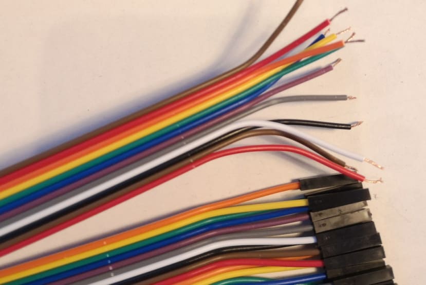
The control board connects to the mainboard via 8x 12-way 2.54mm pitch ribbon cables. These are soldered to the control board and the other end having female connectors to plug into the pins on the mainboard. I had some 40-way jumper wire ribbon cable that had female connectors at each end, so I split it into 12-way strips, cut the connectors off one end and stripped and tinned each wire ready for soldering to the board. Once they were soldered in place I could move on to soldering the sockets for audio out, headphones, power and control voltages.
Testing
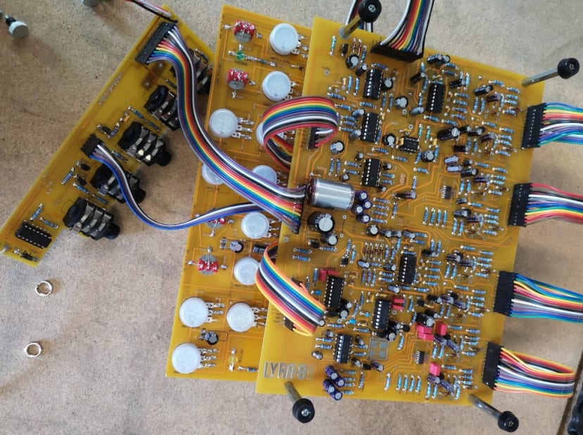
Once the 3 boards were completed I connected them together, separating the main and the control boards with stand-offs, adding some plastic washers to secure the top board and protect it.
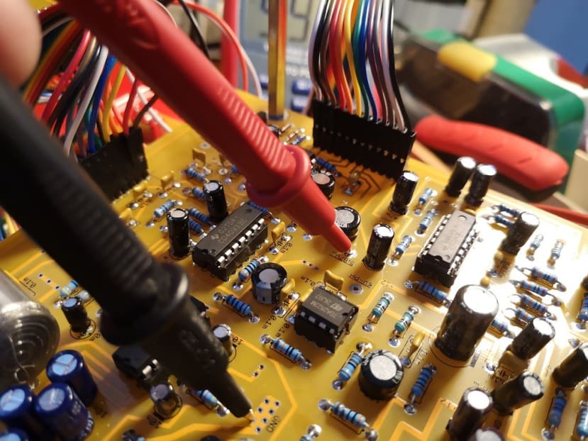
Once I had connected all the ribbon cables I powered the Lyra-8 up and tested the voltages at all the labelled test points. To my relief, all the readings were correct. I connected it to my amplifier and slowly turned up the volume and it made a noise!
It is always a bit tricky to know if everything is as it should be with a project like this if you are not exactly sure how it should sound, so I ran through the “Mastering the Instrument” section of the Manual. What I discovered was that the Hold pots were not having any effect, although everything else seemed fine. I checked all the soldering, particularly on the potentiometers themselves. After an exchange of emails with Soma — who were very helpful, even though they say they do not give support for debugging — I checked all the BC547 Transistors were the right way round and properly soldered, but could not find anything wrong. Having reached a bit of an impasse, I decided to sleep on it and get on with the case.
The Enclosure
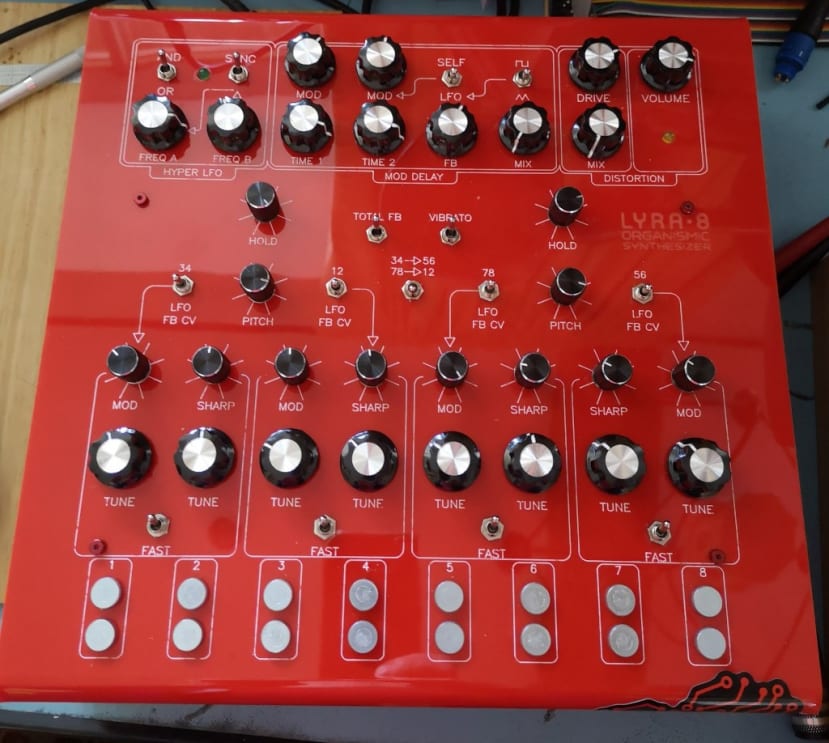
I had decided on a comparatively simple design for the case, using two panels of laser cut and bent acrylic held together with stand-offs. I designed the panels using Inkscape, basing the top on a .dxf file available on the Soma web site. The lettering for the controls would be single line etched and then filled with wax. I predictably went for a red top panel and from experience know that the white infill was the most effective and easy to read on the red background.
I have been working from home for the last couple of months, so I arranged to go into the workshop for a day to use the laser cutter – my first time out of “lockdown” for nearly 9 weeks!
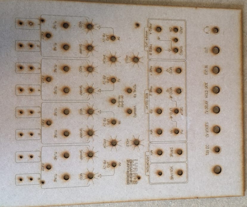
I cut an initial prototype panel in MDF to check that all the holes for switches, knobs and sockets lined up. I hit a slight problem when exporting my design from Inkscape on my work PC to a .dxf file suitable for the laser cutter software, which re-sized it. After some head scratching I realised that I had been using a more recent version of Inkscape on my computer at home and that was what was causing the problem. So I updated the software on the work PC and then everything was fine. I cut the top panel and then bent the top and bottom sections by 90 degrees to form the front and back of the case.
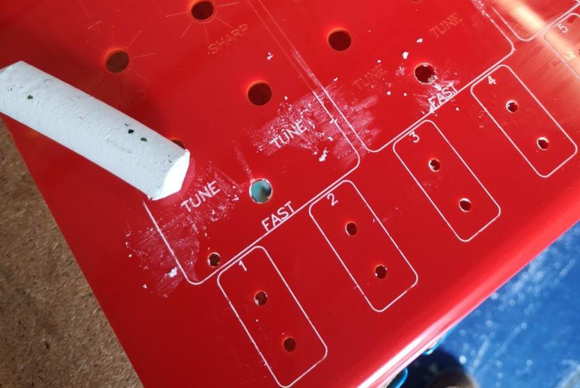
I then filled the lettering with the wax infill stick, following which rubbed it hard with a soft cloth and some mineral oil to fix it in place and remove the excess.
The bottom section I cut from a transparent grey acrylic for a nice contrast with the red. For this panel, I folded sections at right angles again to form the sides of the case.
I then needed to remove all the retaining nuts on the pots and switches, as well as the thumbscrews that form the “keyboard” of the Lyra-8. It took a little bit of gentle manoeuvring to get the PCB in place, flush against the back of the top panel with all the knobs and switches protruding, before fastening them with the appropriate washers and nuts. I then “buzzed out” each of the connections to check nothing had been disconnected.
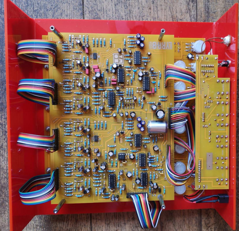
I fitted 4x 30mm female/female stand-offs to the inside of the front panel, through the holes in the control PCB. (The BOM stipulates 25mm stand-offs but I had decided to use slightly longer ones to give myself a bit more space and had made my case slightly deeper to take account of this).
I next fitted the main board to the stand-offs using 4x 35mm male/female stand-offs that would screw to the bottom of my case.
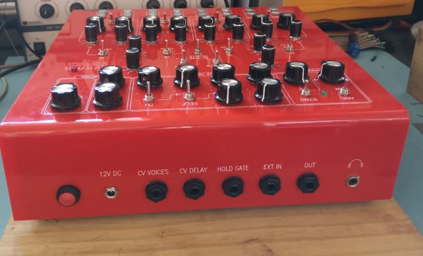
Finally, I fitted the connector PCB to the back panel. I used a nice red Single Pole Single Throw (SPST) Latching Push Button Switch (498-0809) for the on/off button and soldered that in place along with a standard 2.5mm Panel Mount DC Power Socket (048-7842) .
Fixing the Hold problem
Now to get to the bottom of the problem with the Hold control. The Hold potentiometer should cause the voices to sound continuously and adjust the volume of the “drone” – there is one for each group of 4 voices. One of the inputs on the Lyra-8 is for a voltage to control the Hold function. I thought that if I tried using that, it should at least tell me if the Hold is working and help narrow down the problem. As soon as I plugged a cable in the Hold knobs started working – even with the cable not connected to anything else. I suddenly realised what was wrong – I had used switched jack sockets that disconnected the tip of the socket when nothing was plugged in. I replaced the socket with an un-switched one (913-1037) and everything works fine!
Conclusion
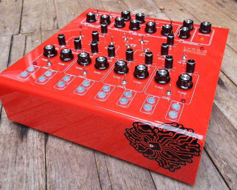
My synthesiser sounds great and looks pretty cool too – the DesignSpark sticker being the final touch. With such a lot of components and soldering, I am relieved that I only had the one silly problem and managed to solve it in the end.
As far as the case goes, I may well refine it slightly, using separate stand-offs to hold the two sections together rather than the ones that support the main PCB. I am also going to look into making a wooden version of the base to give it a bit more weight and rigidity – but woodworking is not my strong point.
The headphone output is a bit noisy, but that seems to be a “feature” of the Lyra-8. It can apparently be cured by replacing the resistors on the two LEDs with higher resistance ones, but this will affect the brightness of the LEDs which are already a little bit dim. Soma’s advice is “First remove the LED and see if noise is alleviated. If so, you can increase the value of current limiting resistor going from LED to ground, start with double the value and work from there, you can find the balance between noise and LED brightness experimentally, also throw a wire from that resistor's ground leg directly to the ground of the power supply jack.” - so I may try that if it gets to be a problem, but I do not expect I will use the headphone out often, if at all.