UAS design and manufacturing from Haggis Aerospace
Follow project Dave from DesignSpark
How do you feel about this article? Help us to provide better content for you.
Dave from DesignSpark
Thank you! Your feedback has been received.
Dave from DesignSpark
There was a problem submitting your feedback, please try again later.
Dave from DesignSpark
What do you think of this article?
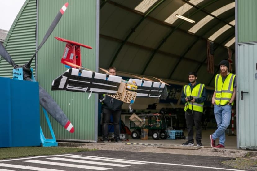 This is the path our team took when designing a UAS for the IMechE UAS Challenge in 2021. Hopefully, it will give you an idea of the design and manufacturing processes.
Concept
First off, to design the drone we had to choose what we wanted our drone to do. The competition is relatively open in terms of design requirements, with the main one being mass less than 10 kg, travel distance of about 1km and max speed below 60m/s.
After a lot of discussions and arguments, we decided to go with a 6kg VTOL plane with a 2kg payload with a cruise speed of 20 m/s. These numbers were mostly eyeballed.
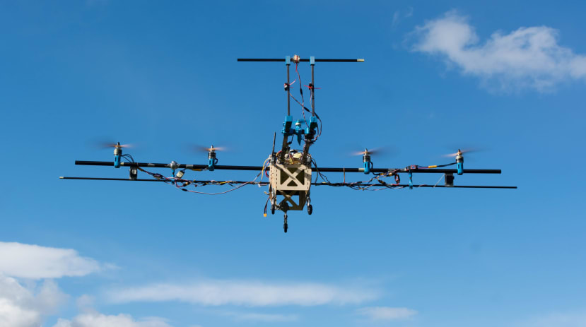
We decided to try an unusual VTOL configuration that involves the whole wing with the attached motors tilting. It was chosen because not a lot of teams do it and it offers interesting advantages compared to other VTOL configurations: in configurations where all motors rotate, you need a servo for each motor, whereas we only need 1, configurations with a fixed quad frame for take-off and a separate motor for cruise suffer from increased drag. Tilt wing configuration comes with flaws too, the main one being stability and lift generated from the motors pointing backwards during take-off. We overcome the stability issue by adding a small motor on the tail for pitch and yaw control during take-off and we ignore the lift problem as it doesn't look too significant.
Design
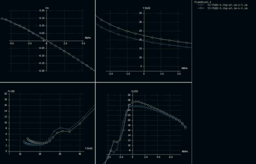
To choose the wing characteristics we go to our good friend XFLR5. It is a free airfoil and wing design and simulating app that we have been using for a while now. There is also Aeolus, but we haven't tried it yet.
An airfoil that looked like it could be good was chosen from the airfoil database and the wing size was chosen to be 2m. A simulation was run with the previously stated constants like cruise speed, weight etc. and it showed that the airfoil we choose wasn’t the best. So we experimented with wing size, chord length and other airfoils until we found the highest coefficient of lift to drag ratio. After that, we added a tail to the simulation and moved it around until the pitching moment was looking right. In the end, we got these fancy graphs and we knew the shape of everything and where it needs to be:
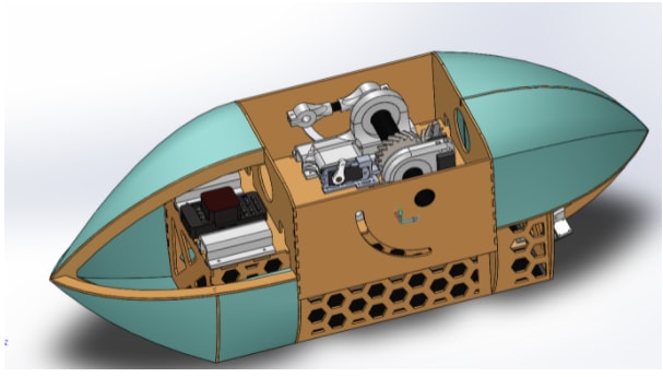
Then we moved into SolidWorks to model everything else. Solidworks is really nice as it allows you to set the density of materials and shows you the estimated weight of your model as well as where the CG is. We had to put our CG as close to the wing's rotation axis, so most of the load would be on the wing motors and not the tail during lift-off. After doing some math and scouting the web we also chose the battery and motors (if you're really curious about those calculations, reach out). The fuselage had to be designed around the payload we were carrying which was basically a box. We also had to keep in mind what kind of materials were available to us during the pandemic. We wanted to make the drone easy to manufacture so avoided super fancy carbon fibre moulds and similar things. Our main materials were: 3d printed parts, laser-cut plywood, hotwire cut foam and premade carbon fibre tubes. The team would get together in discord, talk about our ideas and model the drone or research things. We used GitHub to share files and keep track of everything which worked surprisingly well. After a lot of work our baby was modelled:
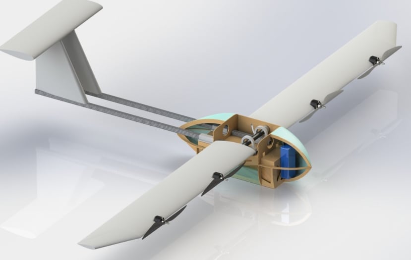
And then tweaked for a few months while we were writing documents for the challenge:
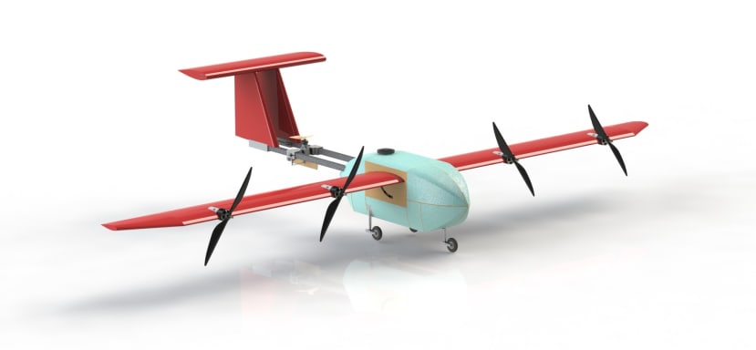
Above is a finished design with everything but the wiring done (which by the way I recommend everyone to do). Next - to build it.
Manufacturing
Carbon fibre cutting can be a bit dangerous because of the dust so here’s how you do it
Carbon Fibre cutting and drilling
The carbon fibre (CF) spars need to be cut to size. This must be done in a well-ventilated area ideally with an extraction unit and an adjustable vacuum, a downdraft table or a partner with a standard vacuum to capture carbon fibre dust. Proper PPE needs to be worn: glasses, at least a p1 dust mask, gloves and ideally a disposable suit. Main risks include skin, eye and lung irritation as well as tiny splinters. Additionally, when cutting with high-speed tools toxic smoke may be produced.
Cutting needs to be performed with the smallest tooth saw available to reduce chipping: a metal cutting or a perma grit hacksaw blade. Alternatively, it can be done with a Dremel or an angle grinder. Cutting of tubes needs to be performed around the tube circumference to prevent one edge from breaking off. Drilling is done with a normal battery drill and a metalworking drill bit. The edges then need to be sanded with 400 grit sandpaper. Here’s how all the tubes look in action.
Fuselage
The fuselage skeleton was laser cut out of 3mm birch plywood parts that easily fit together with cut out teeth and epoxied for extra strength. Laser Cutting was done using a university workshop laser cutter. Alternatively, it can be outsourced to a laser cutting company of which there are many or substituted with a more traditional use of a coping saw if no better alternative is available.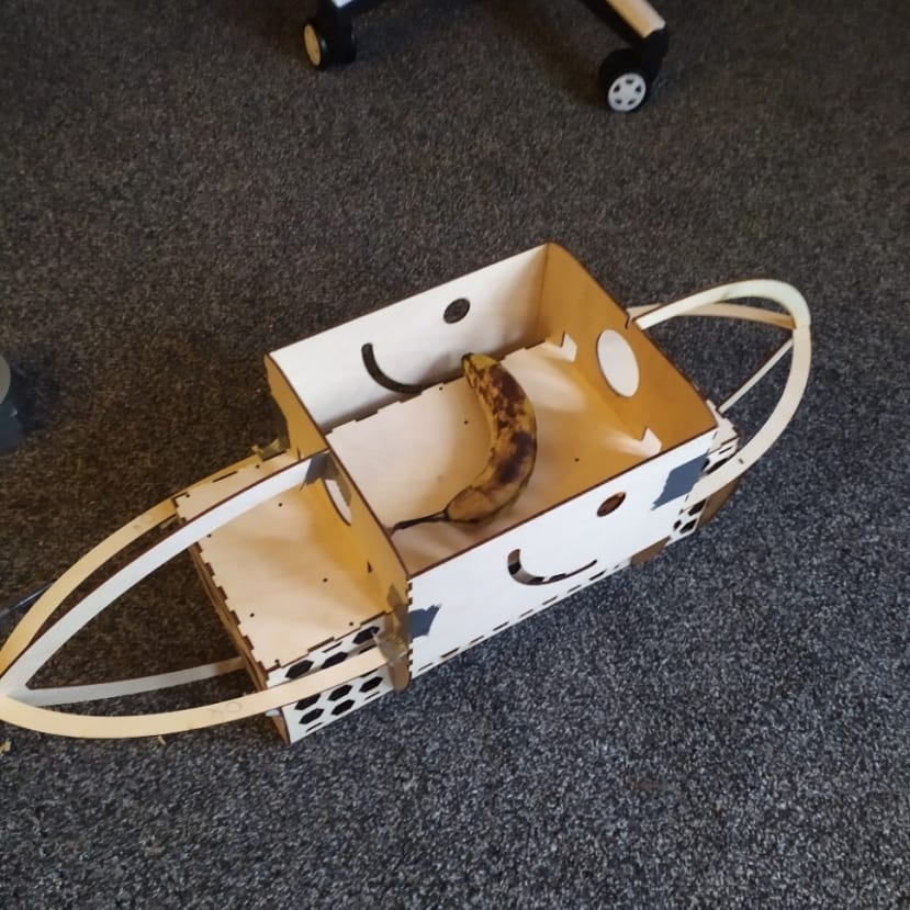
Connectors and holders are 3D printed and attached to the wooden structure using M4 bolts and locking nuts. Note that depending on the printer, air temperature or humidity, parts might warp or shrink, therefore printer settings might need adjusting. The parts were designed with tolerances, however, in our case, all models had to be scaled up by 2.5% to accommodate the shrinking of plastic.
The wing holder spar is cut to size and a single hole is drilled in the middle. The gear and bearings are epoxied on it and the bearings are epoxied onto the 3D prints connectors. Servos are inserted into the 3D printed parts and secured with M3 bolts and locking nuts.
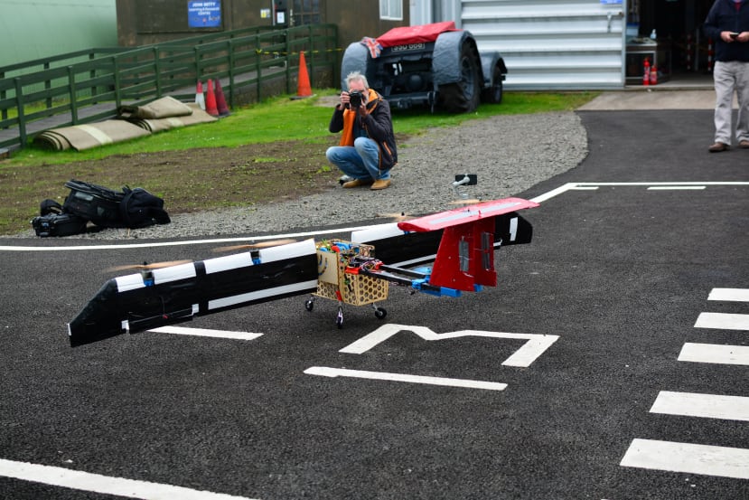
The off-the-shelf landing gear and payload release mechanisms, fuselage plate quick connectors, electronics and sensors are attached with M3 and M4 bolts and locking nuts. The fuselage plates are CNC cut. Alternatively, they can be hot wire cut to give the basic shape and sanded down to get the desired shape. The bottom plates are epoxied to the plywood supports and the top removable plates are inserted in place and secured with a quick connection pin, (we actually didn't have enough time to make the plates so enjoy this 3d render).
Wings and stabilisers
All the wings and stabilisers are made the same way. The shape of the airfoil is laser cut from plywood and used as guides for the hot wire cutter. These include space for the wires running through the wing. Sections of 60cm are cut out and then slid onto the spars. The wing is wrapped in shrinking film (or duct tape) and then space for motors, esc’s, motor mounts, connectors and servos are cut out with a Stanley knife. Ailerons are cut out of the wing with the hot wire cutter and attached with plastic hinges (or duct tape). Pieces of glass fibre are attached with duct tape above esc’s, servos and motors for quick access. The locking mechanism is inserted into the main spars and epoxied. Working with the wire cutter must be performed in a well-ventilated area preferably with an extraction unit or outside while wearing gloves and a respirator. A CO2 fire extinguisher needs to be present in case of an electric fire.
Flight control and electronics
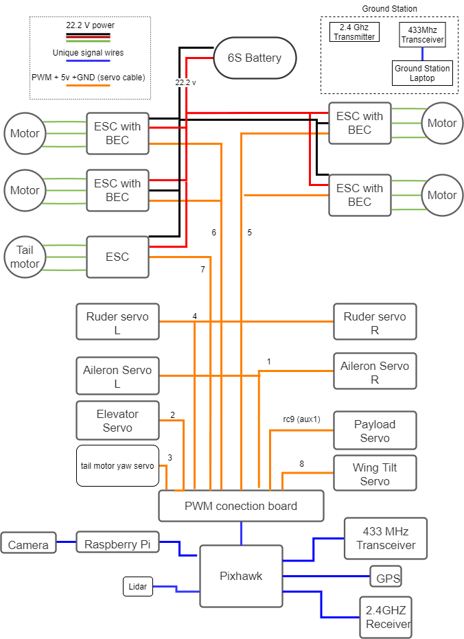
Not much to say here. The autopilot software is premade and is called Ardupilot. We didn't have time to change it, so we rolled with the original one. For the actual flight control, we used a pixhawk 1 controller and the wiki on Ardupilot. We didn't have enough time to tune in perfectly though, which ultimately led to our demise. The electronic connections are pretty straightforward too. The PWM connection board refers to the pins on the pixhawk.
And so, everything was as done as it could be before our time ran out. Vertical flight worked pretty well, but before we could try to transition to horizontal flight it stopped working and decided to do a flip. Next year we might rebuild it but for now, stay tuned for updates and make sure to visit our facebook page. If you have any questions email us at: haggisaerospace@dundee.ac.uk