A Hands-On Look at the STM32 Nucleo Pack for IO-Link
Follow article
 Dave from DesignSpark
How do you feel about this article? Help us to provide better content for you.
Dave from DesignSpark
Thank you! Your feedback has been received.
Dave from DesignSpark
There was a problem submitting your feedback, please try again later.
Dave from DesignSpark
What do you think of this article?
An introduction to IO-Link, the STMicroelectronics evaluation kit, and an example demonstrating the interface.
Introduction
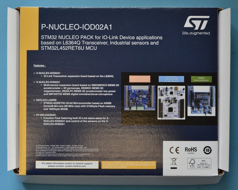
The STMicroelectronics P-NUCLEO-IOD02A1 is an STM32 Nucleo Pack designed for evaluating the ST L6364Q IO-Link transceiver and features a range of sensors plus a demonstration software stack that provides an example IO-Link multi-sensor device node.
What is IO-Link?
IO-Link is a low-cost, bidirectional industrial sensor and actuator interface that helps simplify connections between another Fieldbus, such as industrial Ethernet, and the end device — typically sensors and actuators. Running over common 3-wire cables often used with basic sensors and actuators, IO-Link offers far greater functionality for little extra cost; extended sensor diagnostics, parameter setting and control are all offered.
Widely regarded as a facilitator of diagnostics concepts that are featured in Industry 4.0, IO-Link can bring back diagnostics data to a central location far quicker than sending an operator to check upon a sensor — essentially bringing communications capability to the “last metre” which would typically only carry an analogue or digital signal.
Backwards compatibility is also part of the standard, meaning that traditional binary sensors and outputs can still be used within an IO-Link system. The same also applies to binary IO-Link sensors, which can be integrated into systems that use traditional digital inputs — parameterisation of a binary sensor is still possible, and allows for the settings to be cloned across sensors, opening up the door for productivity increases.
The Hardware
Evaluation Kit
The ST P-NUCLEO-IOD02A1 evaluation kit contains all the parts necessary to get started evaluating IO-Link and running an example application.
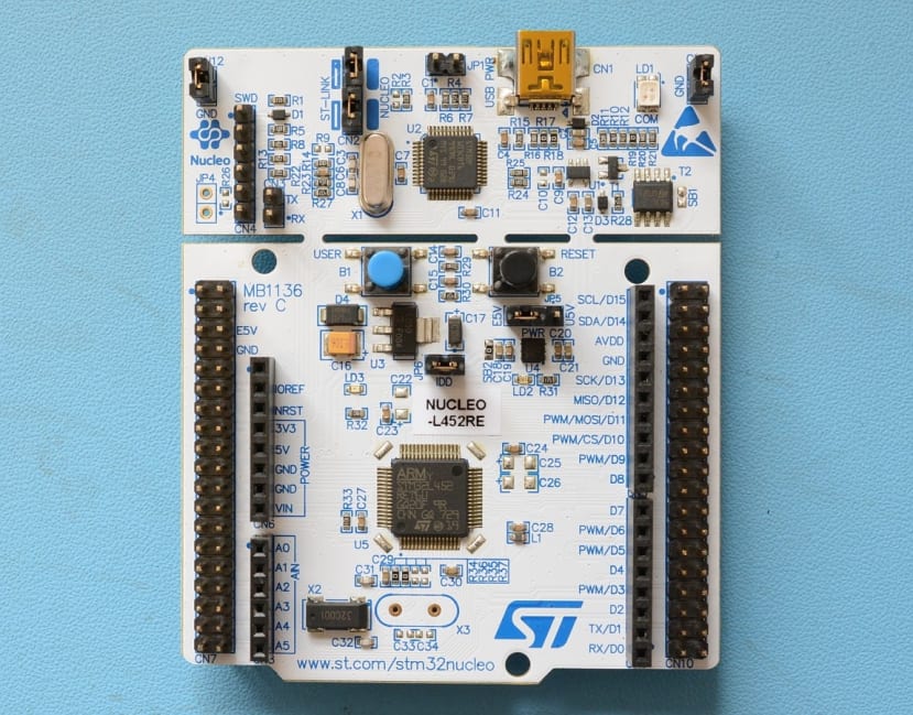
The included NUCLEO-L452RE board contains an STM32L452RE microcontroller, with 512KB Flash memory, 160KB SRAM and up to 83 GPIO. Also included as standard with the Nucleo development boards is an integrated ST-LINK debugger & programmer.
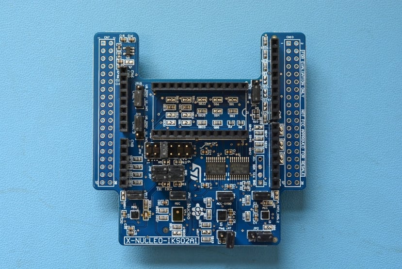
To produce some actual data to be transferred over the IO-Link interface, an included X-NUCLEO-IKS02A1 industrial sensor board is included. This board features a 3-axis accelerometer and gyroscope, 3-axis magnetometer, another 3-axis accelerometer and a digital microphone.
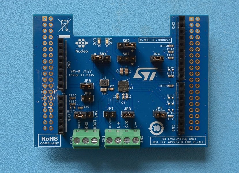
To top off the board stack, a X-NUCLEO-IOD02A1 IO-Link interface board is included. This features the L6364Q dual-channel transceiver specifically designed for industrial sensor applications.
The IO-Link Interface Board
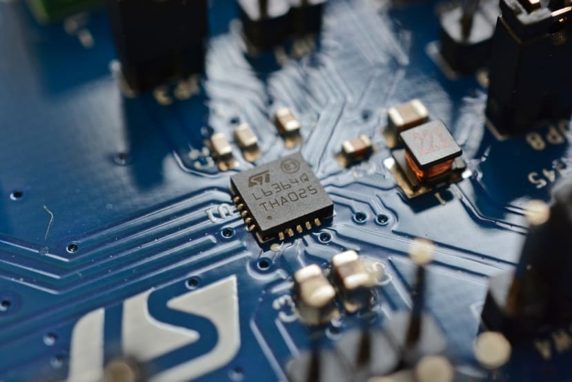
The L6364Q present on the X-NUCLEO-IOD02A1 is an interesting and capable chip — featuring a wide input voltage range of 5-35Vdc, integrated DC-DC regulator capable of supplying up to 50mA between 5-10.5Vdc, on-chip 5- and 3.3Vdc linear regulators, two LED drivers, an SPI interface and a whole host of other features.
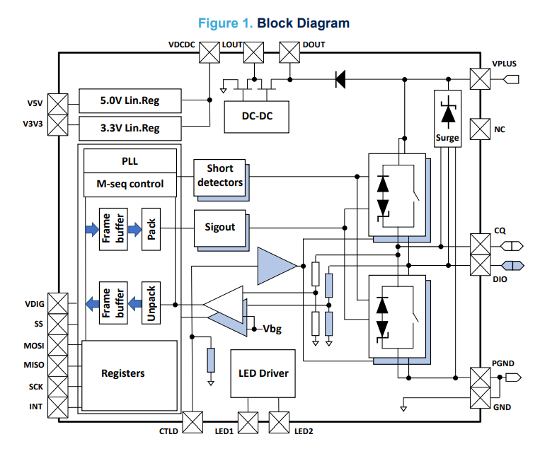
Above we can see a block diagram of the chip, which shows some of the other features such as short-circuit, surge protection and reverse polarity protection. Packaged in a QFN-20L package that is only 4x4mm, and combined with the on-chip power regulation, this is an ideal IO-Link transceiver to design small, capable sensors around.
The chip is also advertised as dual-channel, meaning that there is both a “CQ” IO pin and a “DIO” IO pin. Controllable via the SPI interface, the mode of the DIO pin can be selected between the appropriately titled “DIO” mode; where the pin behaves as a fully-protected GPIO pin, or can be put into “JOIN” mode; which combines with the “CQ” pin to form a double drive strength input/output that conforms to the IO-Link standard.
ST have published schematics for the interface board, available here. Along with this, some sample schematics are also provided within the datasheet of the L6364Q.
Getting Started with the IO-Link Software Evaluation
ST provides a well written, easy to follow getting started guide that details what is needed to test a complete IO-Link system using the board stack.
As we are using the P-NUCLEO-IOD02A1 kit which contains the three boards, all the necessary jumpers are pre-set to route power correctly. To complete the IO-Link setup, a master will be needed — in this case, we are using the P-NUCLEO-IOM01M1 kit which is already flashed with suitable firmware.
Hardware Setup
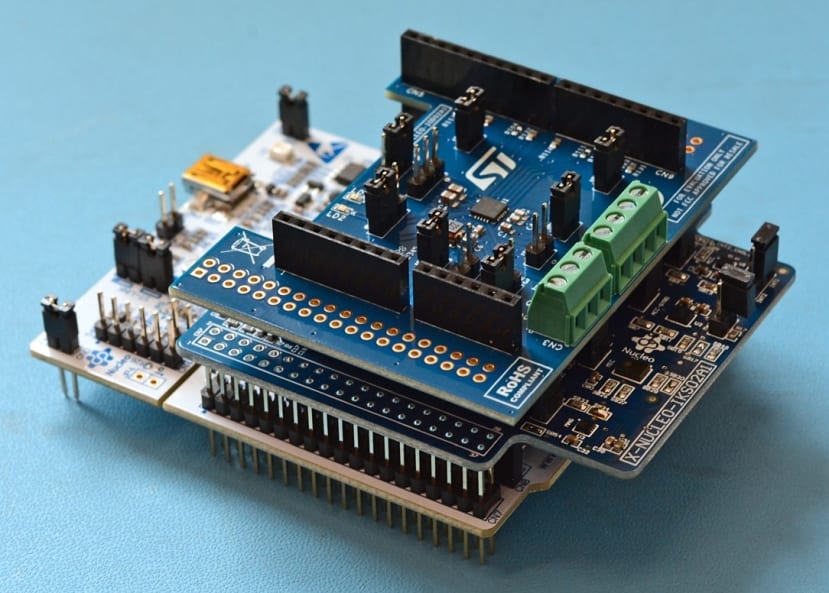
To get started, the expansion boards need to be plugged together in the right order. Starting with the sensor board plugged into the Arduino-compatible headers of the Nucleo board, then the IO-Link transceiver board plugged onto the top of the sensor board.
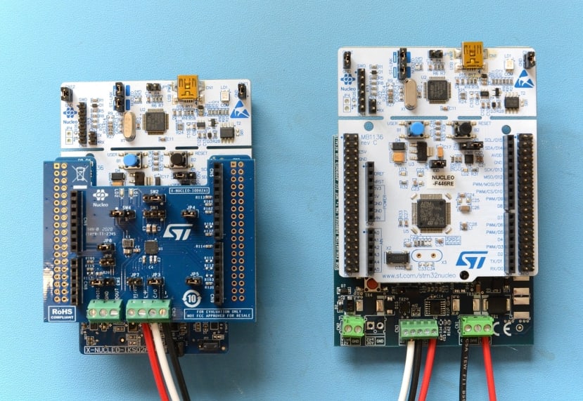
Three wires connected to the L+, C/Q and L- pins of CN2 are all that is necessary to create the IO-Link connection between the evaluation board and an IO-Link master. In our case, we’re using another ST kit — the P-NUCLEO-IOM01M1.
All power is provided via the IO-Link connection, so no other cables need to be connected.
Software Setup
The Nucleo development board provided with the kit is already programmed with a multi-sensor device node firmware, meaning that no actual programming has to be done.
However, if you do want to write firmware for the board, we’ll outline some details about the programming environment below.
Setting up the ST Development Environment
ST provides a suite of development tools called “STM32Cube”, consisting of an Eclipse-based IDE called “STM32CubeIDE” and a graphical microcontroller configuration tool “STM32CubeMX”.
To get started, we installed STM32CubeMX. This is an easy task, although the ST website either requires an account to be created or an email provided to be able to download the software.
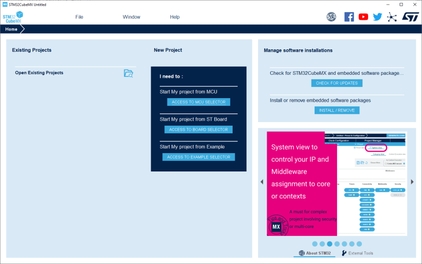
With the software installed, the above screen is first displayed. From here, a new project can be created by either selecting a microcontroller, selecting a board such as the NUCLEO-L452RE, or by selecting an example project.
As we have the NUCLEO-L452RE, “Access to board selector” was picked — boards can be selected through a variety of filters, or searched by board name. With our board highlighted we select the option to initialise all peripherals with their defaults.
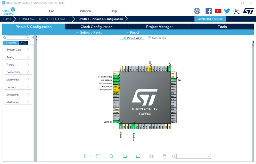
A graphical overview of the microcontroller is displayed, with the currently configured pins displayed. From the left-hand menu, various on-chip peripherals, software middlewares and system configuration parameters can be set up.
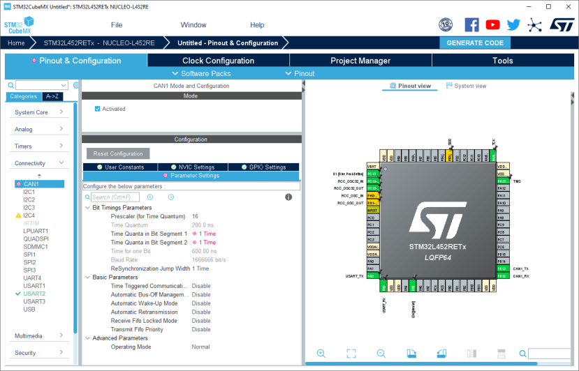
To demonstrate, the CAN peripheral present was enabled for configuration — this automatically enables the pins on the microcontroller. Default values are provided for the peripheral, and invalid combinations are highlighted such as in the image above with the default CAN time quanta.
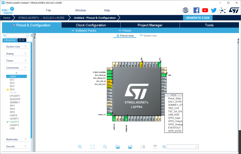
Pins can additionally be configured by left-clicking in the graphical overview. This presents a drop-down menu with the possible functions the selected pin can be assigned.
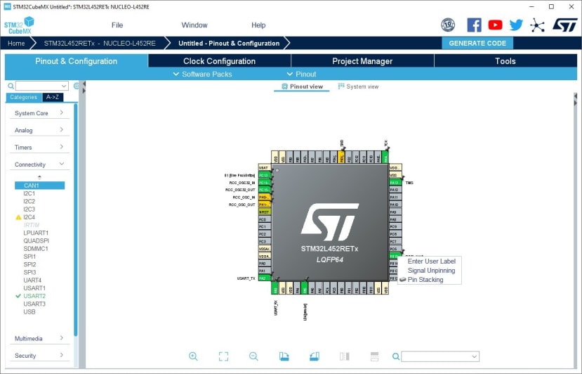
Pins can also have user-assigned signal names applied, which are carried through into the generated code. This is a useful tool as trying to remember that, for example, PB15 connects to a blue LED becomes cumbersome very quickly.
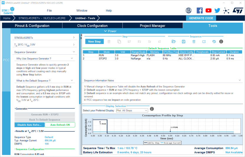
Also included within STM32CubeMX is a microcontroller power consumption estimator. This takes inputs including various different operation steps, battery types and all the previously configured clocks, peripherals and GPIO pins to produce an estimate of power consumption and battery lifetime.
When the microcontroller is configured as desired, a project can be generated that can be imported into either IAR IDE, Keil IDE or STM32CubeIDE.
The project can then be imported into STM32CubeIDE, which is Eclipse-based. The IDE installs all the requisite toolchain components when first installed, so no other additional software is needed to program and debug a microcontroller.
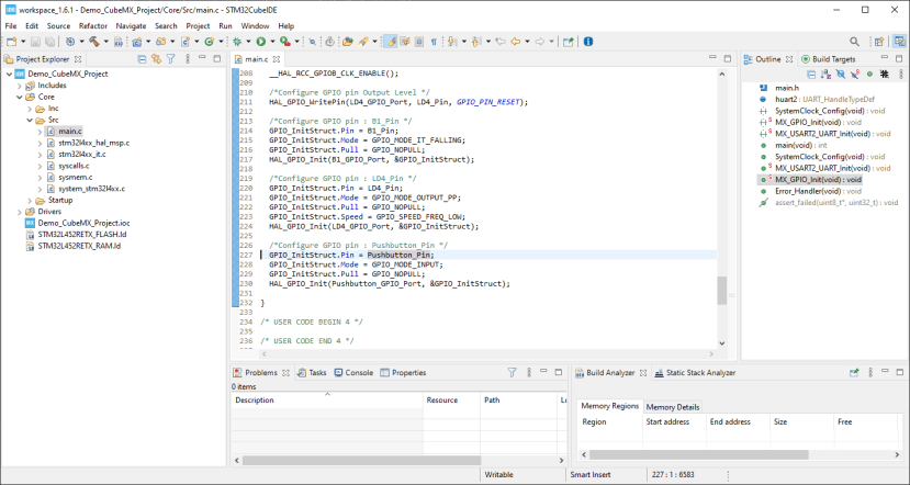
As can be seen above, the pin labels set in STM32CubeMX have been put into the generated code, including both definitions for pin names and pin numbers. From within CubeIDE, the program can be compiled, programmed into the microcontroller and debugged.
Running the Example
As noted above, the Nucleo board included within the kit is pre-programmed with an IO-Link multi-sensor device node demonstration firmware.
IODD File Download
For an IO-Link master to be able to understand a sensor or an actuator, an IODD (IO Device Description) needs to be provided. This is a set of files including an XML-formatted main file containing information on the device identity, parameters, process & diagnostic data and communications properties; several optional language files that can provide translations for the data contained within the main file, and optional PNG-formatted graphics files such as a manufacturer logo and device image.
ST have provided an IODD for the kit on their website, in a function pack that contains the project source code and the file that needs to be uploaded to an IO-Link master. The necessary files are located in the “STM32CubeFunctionPack_IOD02_V1.1.0\Projects\STM32L452RE-Nucleo\Applications\IOD02A1_IKS02A1\IODD” folder.
Viewing Data
With the IODD data downloaded, this can be imported into your IO-Link master software. This should provide a set of parameters and process variables that can be read over the IO-Link interface.
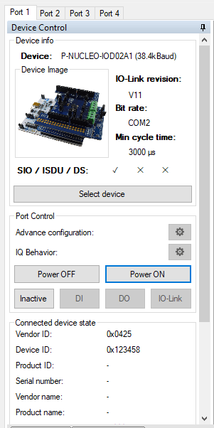
Above, we can see that the IODD data has been successfully loaded, and communications is running. An image of the board stack is provided, along with the connected device vendor and device IDs.
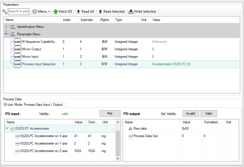
We can also view the output of sensors on the board, above we are looking at one of the accelerometer outputs which includes the X-, Y-, and Z-axis.
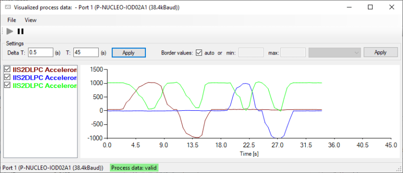
The above image demonstrates rolling the board stack around three axes and plotting the output over the IO-Link connection.
To Finish
In this post, we have taken a look at what IO-Link is, what features ST offer for evaluating IO-Link solutions, the L6364Q dual-channel transceiver and a quick sensor example that demonstrates the usage of IO-Link.