Wireless Power Transfer System for Rehabilitation - 2nd Prototype Development
Follow article Dave from DesignSpark
How do you feel about this article? Help us to provide better content for you.
Dave from DesignSpark
Thank you! Your feedback has been received.
Dave from DesignSpark
There was a problem submitting your feedback, please try again later.
Dave from DesignSpark
What do you think of this article?
Current Sensing, Voltage Sensing, and Power Monitoring
This is the third article in a series. Parts 1 and 2 are available below:
- Wireless Power Transfer System for Rehabilitation - Introduction
- Wireless Power Transfer System for Rehabilitation - 1st Prototype Development
After finishing the motor driving section in Part 2, here comes to the difficult part – the current and voltage sensing.
One of the reasons for doing the current and voltage sensing is that the product is trying to use the information to estimate the mutual inductance and regulate the receiver-side power. By knowing the electrical information of the transmitter, we are able to adjust and change the operating power of the transmitter to regulate the received power on the receiver side.
On the other hand, recognizing the receiver coil position can also be achieved by sensing the transmitter current and voltage. By monitoring the change of current and voltage, it is able to track the output power. When the receiver coil is coupled to the transmitter coil, the amplitude and the phase of the transmitter coil will change. By the change of this information, it is possible to recognize the position of the receiver.
The last - and also the most important - reason is safety. In order to prevent the over-current situation in the transmitter coil, it is necessary to monitor the current in the transmitter coil. Overcurrent in a coil leads to the excessive generation of heat, and the risk of fire or damage to the components.
In order to do the current sensing and power monitor, we tried several different ICs to reach our purpose. LT2940 Power and Current Monitor, AD8216 Current Shunt Monitor and ACS723 Hall-effect Current Sensor we all considered. The ICs have different operating conditions and characteristics. Also, there are some difficulties like the common mode noise, equipment error, component tolerance, etc. At the end, although the power monitor is not completed, the process is recorded as a reference for further development.
The main considerations for selecting a suitable IC are the operating range, the frequency response, and the propagation delay. The reason for selecting ICs by their operating range is that we are trying to minimize the number of components and make the circuit easier to handle. The operating frequency of the coils in this project is 150kHz with ±10V AC. Different ICs will have a different frequency response curve, so it is necessary to confirm the IC has a suitable frequency response for the design. In addition, the propagation delay is important, since the design is trying to achieve a real-time monitor system. If the propagation delay is too long or varied, the result will not be accurate.
LT2940 Power and Current Monitor
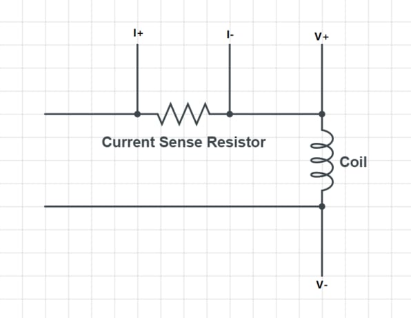
The LT2940 Power and Current Monitor is a Four-Quadrant Power Measurement IC. There are 4 signal inputs needed: V+, V-, I+, and I-. The Voltage sense pin operating range is between -0.1V to Vcc-3V and the Voltage sense differential input voltage range has a minimum of ±(Vcc-3)V, which in this case is ±(10-3)V. The Current sense pin operating range is between 4V to 80V and the current sense differential input voltage is ±200mV. The propagation is 0.7us, but the IC will handle the Current and Power monitoring at the same time, therefore the propagation delay is not significant in this situation.
The problem of the LT2940 power and current monitor is that the signal inputs have some requirement, e.g. the current sense signal needs to be above 4V which mean it is necessary to lift up the I+ and I- which need more component and some special design in the circuit. The second problem is that the IC does not have a high noise rejection rate and easy to be affected by the noise. In this case, the power supply to the LT2940 is not isolated, the transmitter coils are operating between ±10V which make some noise. As the result, the outputs of this IC are too noisy and not acceptable.
ACS723 Hall-effect Current Sensor
The ACS723 has 5us propagation delay, which is 70% delayed to the actual current. It works accurately, but the result is delayed which is not suitable for the design.
AD8216 Current Shunt Monitor
The AD8216 can be a current shunt monitor. The propagation delay is 100ns which will cause a 1.5% delayed in the result. The common-mode rejection ratio (CMRR) is ~60dB at 150kHz which is better than LT2940. The gain of the IC is 3V/V. The IC is selected by its small propagation delay and higher CMRR. Since the IC is only a current shunt monitor, it is needed to combine with a Multiplier to have a monitor for the power part. The AD8216 is an easy-to-use IC, however, to be careful with the value of the current sense resistor. The IC has a gain of 3V/V, the output is limited to the supply voltage (5V). To have a better and accurate result, it is necessary to know the current range in the application and select a suitable value for the current sense resistor.

Following trials, we agreed to use AD8216 in the final version for current sensing. The current sensor is followed by a common peak detector. And it will be discussed more in the coming articles.
If there is any better solution for the power monitor, please comment and let me know. :o)