Wi-Fi as the primary communications protocol in battery powered IoT devices – Does it work and how to reduce power consumption? - Part 1
Follow article
 Dave from DesignSpark
How do you feel about this article? Help us to provide better content for you.
Dave from DesignSpark
Thank you! Your feedback has been received.
Dave from DesignSpark
There was a problem submitting your feedback, please try again later.
Dave from DesignSpark
What do you think of this article?
Intro
Would it be possible to publish sensor data from a microcontroller to a database using Wi-Fi as the primary means of data transport? As a person with some knowledge in home automation and with a general obsession to put sensors on everything… I was curious to know if it would be possible to run an ESP8266 (124-5505) , with a relay of sensors, on a battery and get a decent battery life relieving me of constantly having to run around and servicing the units.
An ESP8266 is, as most of you probably already know, a small microcontroller with built-in Wi-Fi capabilities making it quite suitable in general to post and receive sensory data when there is a solid power connection present.
Now, many might wonder why I chose to use an ESP8266 instead of an ESP32 or why not even leave the whole Wi-Fi category of controllers and go with an entirely different protocol like Zigbee, LoRa or perhaps even BLE which are protocols known to draw substantially less power during transmission. This would certainly make the challenge of a sensor running entirely on battery power easier! But since I have the tendency to order a bit too many components in general or specifically in this case, ESP8266’s, I now find myself trying to figure out what to do with them all.
I have in the past built some, what I would call “sensor hubs”, reading the usual suspects temperature and humidity in different rooms and places around the property. These units have also been combined with relays for the added functionality of being able to control everything from lights to lawn sprinklers to water fountains. All of these hubs have one thing in common however, they all run on mains electricity. This has worked just fine and I’m probably not going to move these devices over to battery power any time soon. Nevertheless, in the cases where I would like to have sensors but don’t have access to power a battery-powered alternative would be very nice.
Perhaps I should explain shortly what infrastructure I currently have in place for receiving and displaying the data read from the sensors. I recently upgraded my entire network with the intent to get a good and strong Wi-Fi signal all over the property. For all of you who are curious/interested, it is a full-on Ubiquiti setup with 6 access points strategically placed around the estate. Other than this I use a hardwired Raspberry PI 4 with the “OpenHab home automation server” installed, which basically is a software that makes it easier to connect to smart devices and control them all from the same place. There is also great functionality for time-based events controlling and nice ways to present the data in customizable GUI’s. On the Raspberry, there is also an MQTT server (Mosquitto) installed, which basically runs the whole show when it comes to sending and receiving data from all of the sensors
How to reduce power consumption
The previously mentioned sensor hub does nothing to reduce the power consumption, which when you think about it really isn’t that big of a deal since the consumption can almost be neglected when compared with the cost and availability of mains electricity. However, if the same unit were to run off a battery this story would probably take a turn for the worse. Depending (of course) on the type and size of the battery connected it would be possible to get a longer or shorter lifetime before a change is necessary. But if one wishes to have a combined unit that isn’t the size of a small lawnmower, reading the temperature and humidity, we probably need to look into how we can reduce the power consumption.
There are a few things that come to mind when thinking about this. Most microcontrollers have a sleep functionality which basically makes the controller go into dormancy when it’s not used or when it’s waiting to run the next line of code. The ESP8266 has a few different sleep modes which per my understanding can be divided into modem-sleep, light-sleep and deep-sleep. Modem sleep is basically turning off the modem, but it’s still connected to the Wi-Fi network through a DTIM beacon mechanism which I can’t go deeper into since I don’t quite understand it. It’s initiated by calling the command Wi-Fi.mode(WI-FI_OFF); followed by WiFi.forceSleepBegin(); and then to turn on the modem again the WiFi.forceSleepWake(); should be called. Light-sleep is similar to modem-sleep with the main differences being that the ESPs system clock is turned off, and the internal CPU is suspended. In this state, the ESP will not respond to any signals or connected interrupts. I’m not quite sure how this should be implemented but my understanding is that it’s initiated by calling wifi_set_sleep_type(LIGHT_SLEEP_T); and disabled with wifi_set_sleep_type(NONE_SLEEP_T);
Lastly, there is the deep-sleep mode, this will turn off everything except for the RTC (Real Time Clock). The deep sleep can be initiated with the ESP.deepSleep(uint32 time_in_us); command and when the RTC reaches the specified time in nanoseconds it will send out a pulse on the D0 pin. This means that you have to physically connect the D0 pin with the RESET pin of the ESP. The clock can only count so far in deep-sleep mode so there is a limit in how long it can stay in deep-sleep using the internal clock, which is roughly 71 minutes.
With this in mind, I came up with a set of test configurations, all of which had the exact same hardware but running on different sets of code. I also thought that it would be interesting to compare the potential improvements with some sort of baseline which in this case would be the code that I normally use without energy optimization in mind. So, the first configuration/set of code is basically my usual approach when sending and receiving sensory data which will be described below together with the other configurations.
Code Configuration 1
This code connects to Wi-Fi and the MQTT server and sends the sensor data every 30 seconds. If either the Wi-Fi or MQTT connection is lost at any point it tries to reconnect instantly. There are some changeable parameters such as sending interval, and whether or not the code should use a timer or a delay in between transmissions. I had a thought/theory that there might be a difference in processor load between using a timer and a delay, and thus impacting the power consumption.
Pseudocode
Boot → Connect to Wi-Fi → Connect to MQTT server → Read data from sensor → Send data to server → Wait 30 seconds → Start over from “Read data from sensor”
Code Configuration 2
This code connects to Wi-Fi and the MQTT server and sends the data every 30 seconds however unlike the previous version this code does not maintain a solid connection to the server infrastructure in between transmissions and thereby, in my mind at least, reduce the power consumption. Since I expect these to be the most power-hungry parts of the program. So, in other words, the code will disconnect from the server and Wi-Fi as soon as the data has been transmitted. This configuration has the same changeable parameters as the previous one.
Pseudocode
Boot → Connect to Wi-Fi → Connect to MQTT server → Read data from sensor → Send data to server → Disconnect from server → Disconnect from Wi-Fi → Wait 30 seconds → Start over from “Connect to Wi-Fi”
Code Configuration 3
This is the first configuration that implements the deep-sleep functionality, it does the same thing as in the previous configurations but instead of halting in between transmissions, it goes into a deep sleep for 30 seconds before starting all over again. The only parameter that can be changed here is the time in between sending data.
Pseudocode
Wakeup → Connect to Wi-Fi → Connect to MQTT Server → Read data from sensor → Send data to server → Disconnect from server → Disconnect from Wi-Fi → Reset timer → Sleep 30s → Start over from “Wakeup”
The reason for the short interval of 30 seconds between transmissions is that I plan for shorter tests running between 5-15 minutes. Later I will then be able to use math and make approximations and extrapolate the consumption during a typical day and then hopefully be able to compare this with different battery volumes. Thus, the time until a battery change is needed can be calculated for different intervals and the different code configurations.
Test setup
Now on to the test setup, as previously mentioned I will use an ESP8266 as the main microcontroller. More specifically I will use a Wemos D1 mini prototyping board with an external antenna, to this controller a sensor is connected which in this case is a DHT22 temperature and humidity sensor. For analyzing the consumption and getting a deeper understanding of the power usage of different stages in the code I will be using the Otii Arc (192-3400) and the standard perpetual Otii software by Qoitech. This has the benefit of being able to record and plot current consumption and voltage over time, there is also a nice feature that synchronizes the serial communication and codes it to the matching timestamp of the current/voltage plots. Making it possible to see almost exactly which part of the code is responsible for the corresponding current draw.

If for some reason the Wi-Fi access point is malfunctioning or is powered off during a power outage the ESP must be limited to a maximal number of re-connection attempts before giving up for some time. If this isn’t implemented the device's battery will be drained almost instantly not knowing that it’s not a fault of the ESP rather than a fault of the Wi-Fi infrastructure. This should also be implemented, for the same reasons, to the code handling the server connection. This safety feature was included in the second and third configuration of the code. The ESP was limited to 20 reconnection attempts with a delay of 500ms in between each attempt.
Now short about the libraries I chose to use in the code <ESP8266WiFi.h> is the first and perhaps the most important one, it is the prefered library for controlling and communicating with the ESP’s modem. <PubSubClient.h> is the library used for communicating with the MQTT server, <DHTesp.h> is the final library used for reading data of the DHT22 temperature and humidity sensor.
Some thoughts before testing
Alright, so before we move on to the test results, I figured that I should give a brief explanation of what I expect from these tests. The short answer is that I expect the power consumption to decrease as each code configuration is tested, in other words, the first configuration should draw the most and the last configuration should draw the least.
I should probably also elaborate my thoughts behind the difference between using a delay and a timer in between transmissions. The first option is to use a delay which is almost always done by calling the delay(milliseconds); in the code. This will result in the processor halting somewhat, nevertheless, I’m still aware that some functionality is still present since the microcontroller can handle attached interrupts during this delay time. Later I also learned that the modem of the ESP will take advantage of this delay for establishing communication/keeping the connection to Wi-Fi, but more on that later.
The other alternative is to use a form of timer, and what I mean by that is using the built-in function “millis()” to get the number of milliseconds since the device was booted up. In this way we can compare the milliseconds with a fixed time in the future and every time we pass this value the code for handling transmission is executed and the future time value will be updated with some time added to it.
The second alternative is great if the microprocessor needs to be doing other things in between the sending of data e.g. responding to an http request or likewise. However, my initial thought is that the power consumption should/could be higher using this method. Although this is just an assumption since I’m not sure exactly how the “delay(ms)” function is working.
Results after the first test
Recording the consumption, during 10 minutes with a transmission interval of 30 seconds, using the Otii Arc gave the following data/result. The software allows for superimposing these recordings, and it is also possible to offset each recording so that the graphs are synchronized. An example of this can be seen below.
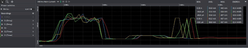
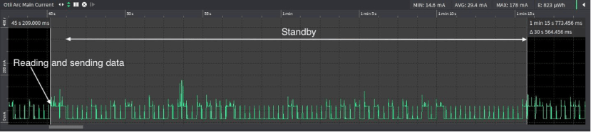
This is great when trying to analyze the current in-depth, however, I found that in this case most of the recordings are quite messy with a lot going on in terms of the current draw over 30 seconds so this would result in an overall messy graph. I will therefore show each recording by itself with the typical transmission and standby pattern selected as an interval in the graph.


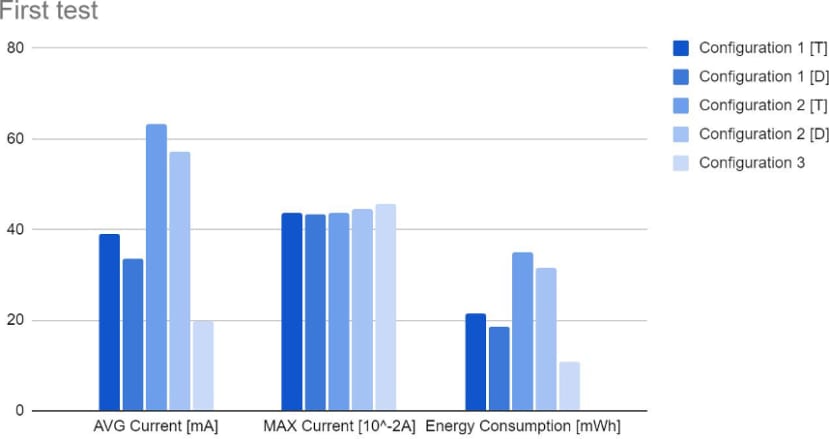
The results are somewhat different from my initial thoughts. Perhaps not really between configuration 1 and 3, since the consumption was reduced by roughly half which is great. It’s rather the difference between the first and second code configurations that are a bit confusing. It seems like the second configuration is drawing substantially more power, which contradicts my initial expectations. However, I do believe that the cause of this is related to issues regarding Wi-Fi connectivity, looking through the recorded logs and graphs it seems like the ESP is using most/all of its allowed reconnection attempts in both configuration 2 and 3 thus greatly increasing the power consumption during the active part of the code. This can be seen quite clearly in the picture below showing a failed transmission attempt for configuration 3 with deep sleep implemented. I also noted that the maximum current usage increases for each configuration change. I think that this has to do with when in time the boot, Wi-Fi modem turn on and the Wi-Fi connection is initiated. In that case, it would make sense that the last configuration has the highest max current since everything will happen at the same time every time in that configuration. Whilst in the first configuration the boot spike will happen once, then the modem turns on and lastly a Wi-Fi connection attempt is made. After that only the Wi-Fi spike will return on a regular basis.
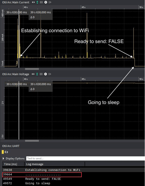
When looking at the second row in the UART section (Time = 39664 ms, marked with a red rectangle), it is possible to see all the connection attempts that were made. Each dot represents a connection attempt and as previously mentioned I limited the connection attempts to 20 with 500 ms in between. Since it uses all 20 attempts a failure flag is set and the ESP goes back into sleep. There were similar findings in both tests using configuration 2 with a timer respectively a delay implemented, but it was easiest to see in this particular recording of configuration 3 which is the code with deep sleep implemented. This, unfortunately, resulted in that most times no data was sent to the server, which is quite concerning since that’s the whole point of the device/program.
I couldn’t find a specific reason for the connectivity issues other than perhaps the signal strength is a bit too weak in my testing location. The result of this is me now questioning the validity of these results. I don’t think that this is a fair comparison which in turn led me to take a deep dive into how a Wi-Fi connection is established and handled by the ESP thus breaking down the code into separate parts to better understand what is happening. This is what I will be doing in Part 2 of this article, then for Part 3, I will be estimating battery life for a couple of batteries with Otii Battery Life Estimator that comes with Otii Arc (192-3400) standard perpetual software, hopefully answering whether Wi-Fi could be an option as a primary communications protocol in battery-powered IoT devices.
Lastly, it is also possible to observe that it seems to be beneficial to use a delay instead of a timer according to these results.