The Tolerant Engineer
Follow article
 Dave from DesignSpark
How do you feel about this article? Help us to provide better content for you.
Dave from DesignSpark
Thank you! Your feedback has been received.
Dave from DesignSpark
There was a problem submitting your feedback, please try again later.
Dave from DesignSpark
What do you think of this article?
In my last post, The Inventor and the Engineer: Hare and the Tortoise, I started to examine the challenges facing the crowd-funded Maker when attempting to turn a prototype into a product. It ended with a slightly tongue-in-cheek analysis of customer types and a promise to add some engineering detail. Well here we go.
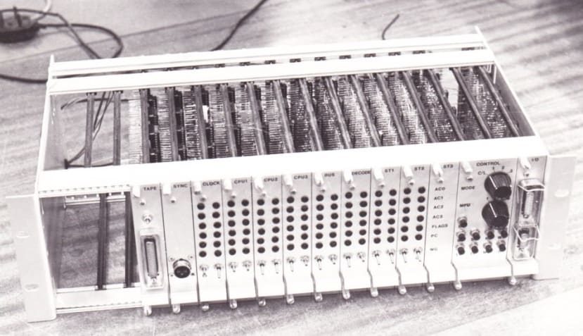
Cyclone: Prototype for a transient-fault-tolerant train-control computer
First principles of electronic hardware/software development
Step 1: Power-up the project prototype and notice that things (very) rarely work first time.
Step 2: If it does work first time, it won’t at an important demonstration and you’ll wish it had failed at Step 1.
Step 3: If it still works at the demonstration, then customers will experience the bugs and they will wish it had failed at Step 1 or Step 2. And so will you.
Step 4: There is no Step 4, unless you work for a very large global company (but not for long).
Many an undergraduate student has experienced the trauma of Step 2 with their final-year project. Those that have are better for it, having received a vital lesson in ‘Real-World’ engineering. In most cases, the students whose designs work as soon as they are switched on, are just plain lucky. Hardware design becomes a lot more complicated and time consuming once the ‘lash-up’ or early prototype has to evolve into a saleable product. First comes component tolerancing, then environmental (principally temperature) considerations and finally compliance with EMC and where applicable, Functional Safety standards.
Component Tolerancing
No components are perfect. A 1kΩ resistor will have a tolerance value, for example ±10% which means that a particular component might have an actual resistance of between 900 and 1100Ω. The same principle applies to capacitors and inductors. Near exact values might be critical in an analogue filter for example, to ensure a particular cut-off frequency, so close-tolerance components may be needed. These will be relatively expensive so ‘tolerancing’ will ensure that money isn’t wasted on over-spec’ed components.
Real active components also have characteristics that differ somewhat from theoretical ideals. The classic operational amplifier has in theory, infinite input impedance and infinite open-loop gain. A look at the datasheet for the venerable 741 part will show how untrue that is! Modern op amps are much nearer to the ideal, but still not perfect.
Even logic with its two-state, on or off signals needs careful design. Two things to remember (at least): For nominal +5V TTL logic, a logic 0 is anything below about 800mV and a logic 1 is anything above about 2V. Typical levels are around 200mV and 4V respectively. Secondly, there is a delay between the input to a gate changing and the output switching, called the Propagation Delay. There it is on the datasheet: tPD. Depending on the technology, for a simple gate it might be picoseconds; for a complex logic part, much, much longer. So often it gets forgotten in the feverish excitement of cobbling some logic together. The nasty thing is that the circuit may seem to work at first, then the next day when the room temperature has fallen or there’s a full moon, it won’t. Many an undergraduate final-year project has fallen foul of this on demonstration day, particularly those involving some discrete logic components (gates and clocked latches or counters).
The Race Hazard
The race hazard is one of those nasty, hard to diagnose problems that Propagation Delay can cause, made worse by slight production variations between chips of the same type. Basically, if a logic signal can take different paths through some logic gates you must take into account that one path will have a larger cumulative propagation delay than the other. If each path ends in an input to the same 2-input gate for example, then the gate output may exhibit a brief pulse with the same width as that propagation delay. That pulse may only be nanoseconds or even picoseconds wide, but that’s enough to provide a spurious clock to a pulse- or edge-triggered device. The race hazard can be a nightmare to spot and the best way to avoid problems is with good design at the outset. A tip: don’t try padding out pathways to equalize them – that way lies insanity. Your design must be ‘time-tolerant’ which means that data is only read-from, or written-to latches on the rising or falling edges of clock signals. The interval between clock edges is set to ensure that data pathways with the longest propagation delays have settled down and any ‘glitches’ are ignored.
Environmental Conditions
All electronic components are specified to operate over a range of ambient temperatures. Here are the four ‘standard’ ranges, although manufacturers often come up with different ones when they just can’t get their chip to work over one of them! At the outset the designer must decide which of these target customers they’re going for and select compliant components accordingly. Temperature tolerancing is often forgotten at the prototype stage when the ambient is assumed to be about 25°C in the lab. No problem for a domestic gadget but if it’s destined to go under the bonnet of a car then make sure the higher-temperature versions of the chips are available - and costed in. Note that the commercial range only goes down to 0°C so if the target application is an outdoor weather station in a temperate climate, well, you might just get away with it….
Once again, there are further complications: most ICs will be specified with an operating temperature range because the maximum power dissipation for the device is known and accounted for. Many ‘power’ devices such as big MOSFETS and diodes will probably just have a maximum junction temperature, TJ, usually around 150°C. This is because the circuit design will determine power dissipation and how much heat needs to be removed using heatsinks, fans or combinations of the two. This situation also applies to modern multi-core microprocessors where how hot it gets depends on the clock speed and the number of cores in use.
Consequences of ignoring temperature ratings
Overheating reduces the life expectancy of a semiconductor chip at best; at worst it can literally burn out in the first few minutes of operation. Maybe you can get away with potential overheating on a domestic microprocessor-based gadget which probably won’t use all the cores anyway, or which will quickly be made obsolete by the next model. This approach could prove disastrous in industrial, automotive or military applications where high-reliability over long periods is expected.
Mechanical Issues
Another source of misery to project students lies at the interface of the electronic components and ‘mechanical’ ones. The humble pushbutton switch seems so benign, but it can cause random havoc unless tamed by appropriate hardware/software. For more than you’ll ever want to know on this deceptively simple subject see my DesignSpark blog post: ForthdsPIC and a Kill Switch.
Electromagnetic Interference & RF Emissions Compliance
“RF emissions? What RF emissions?”, I hear you say, “my project doesn’t involve wireless communication”. If you’ve got a microcontroller being clocked in the hundreds of MHz, then you have a pretty good radio transmitter. It doesn’t matter on the lab bench, but once it becomes a saleable product which interferes with the customers’ TVs and WiFi, then you’re in big trouble. You will need to submit your product for EMI testing at a certified laboratory and this costs a lot of money and takes a long time. Should it fail – and it probably will – re-work and re-testing will see you seriously out of pocket and behind schedule. An obvious thought is to do some EMI testing yourself to get your device into a state where it should pass the official test. This is called Pre-Compliance testing and will require the purchase of some specialist, but not too expensive test gear. Often sold as a kit for the purpose, what you get is essentially a radio receiver with an antenna in the shape of a wand like those used for security body-searches. Waving the wand around your device while it’s switched on and running will allow emission ‘hot-spots’ to be identified. It’s not precise, but will massively increase the likelihood of a ‘passed-first-time’ result at the official test. Read this article: Most IoT Devices Initially Fail EMI Testing for some more information.
Calibration
Not all products require calibration, unless of course the function is to take measurements. Even then, the accuracy of modern ‘digital’ designs may depend only on the frequency and stability of a quartz oscillator. These can be supplied calibrated with accuracies in the fractions of 1% for very little cost. This is OK if the parameters being measured are simple and fundamental; voltage, current, frequency, temperature for example. But if you’re developing an air pollution measurement gadget what then? The sensor outputs will almost certainly require to be calibrated against reference air samples contaminated with precisely known quantities of each pollutant. You will need a lot of very expensive laboratory kit. I mention this example, because I know of at least one such crowd-funded gadget that ran into big trouble just before production because nobody had thought about calibration….
Tolerating Faults
It’s unlikely that the latest hardware for autonomous cars will be crowd-funded. This is an example of an application covered by Functional Safety, which means that you must use methodologies to avoid creating bugs. If bugs do get past this design process, then the standards dictate that they must not cause catastrophic failure. In other words close to 100% of all possible failure modes must be detectable by the hardware itself, making it Fault Tolerant. The main standards involved are IEC 61508 for general industrial applications and ISO 26262 for the automotive market. This white paper: Embedded Architectures Supporting Mixed Safety Integrity Software will provide an idea of what’s involved.
And Finally….
Searching for a book in the junk-pile that is my study/home lab the other day, I came across a set of old photographs, one of which heads this blog post. It’s the prototype main processor unit for Cyclone: a transient-fault-tolerant train control computer based on three National Semiconductor INS8900 16-bit microprocessors. It formed the basis of my PhD thesis in 1981 and could run three independent programs with full error checking and automatic re-try. I mention it in the context of design cock-ups, in this case a nasty race hazard in the control circuits. Initial test runs showed no errors in the checked program outputs, but something was wrong – the output results, while correct, seemed to be coming at slightly varying intervals. I added a monitor to the internal error counters and straight away saw mistakes being made and re-try cycles initiated. My machine was rather more fault-tolerant than I thought, even able to compensate for design mistakes! A re-work of the control logic yielded a much more elegant and race-hazard free design. After that, I built a box which brutalised the power supply rail with variable frequency and duration drop-outs. It was amazing how bad the power rail could get before throughput dropped below a useful level. I was lucky: design mistakes like that can lead to many hours/days of fruitless debugging.
If you're stuck for something to do, follow my posts on Twitter. I link to interesting articles on new electronics and related technologies, retweeting posts I spot about robots, space exploration and other issues.