Showcasing RS Pro Thermal Imaging at Electronica 2022
Follow article
 Dave from DesignSpark
How do you feel about this article? Help us to provide better content for you.
Dave from DesignSpark
Thank you! Your feedback has been received.
Dave from DesignSpark
There was a problem submitting your feedback, please try again later.
Dave from DesignSpark
What do you think of this article?
Building a demonstrator that showcases RS Pro Thermal Imagers for diagnosis of failing bearings.
Introduction
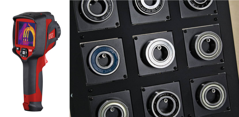
We worked together with the team at RS Pro to create another demonstrator to exhibit at Electronica 2022, this time showcasing one of their thermal imaging cameras with the use case of diagnosing failing bearings.
The Idea
The brief consisted of a grid of bearings and a push button that would select a random bearing to be heated up, simulating a slow failure which could be identified using the thermal camera. This is a good demonstration of the usage of a thermal camera for predictive maintenance and one that is commonly found on a factory floor.
The selected RS Pro thermal camera (227-5213) boasts a wide feature range including two temperature measurement ranges of -20 to +150°C and 0 to +650°C, a 384x288 pixel thermal sensor resolution, on-board WiFi and a thermal frame rate of 50Hz. Video capture is also supported, along with an app for mobile devices that allows for viewing of the video stream and image transfer.
Initially, this sounded like an easy-to-implement idea, but the reality turned out slightly different. The main challenge we encountered was heating the bearings — a number of different bearings were supplied in varying sizes that would make individually attaching heaters to each one difficult. We instead opted to have the bearing sit on a plate that would conduct heat through, which simplified the design.
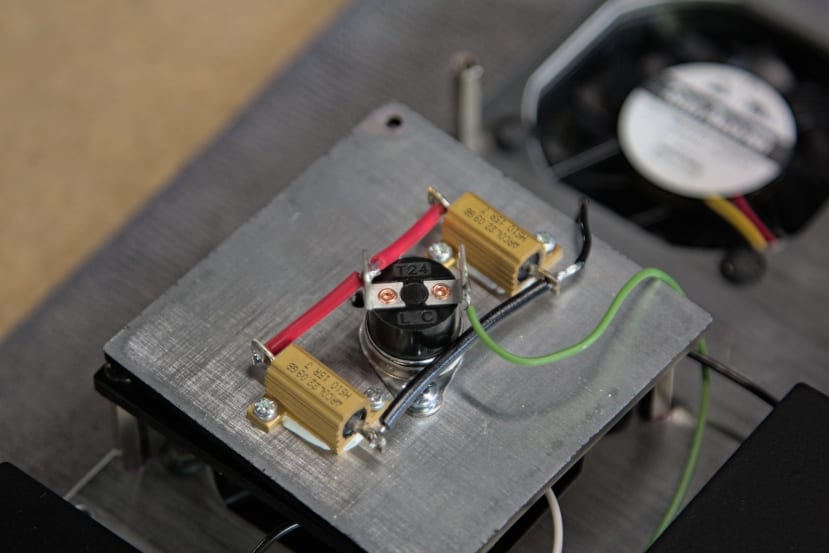
Two 15 ohm, 10W power resistors (016-0332) were selected and pressed into service as heating elements, capable of raising the plate to 40°C in approximately one minute. The aluminium case of the resistors provides a convenient mounting solution and a way to couple heat into the bearing plate when combined with a small dab of thermal paste. A value of 15 ohms was decided upon to provide adequate heating power, whilst also not exceeding the 10W power rating.
Passively cooling the plate back to room temperature took longer than expected (on the order of 10-15 minutes) so a 60mm 12V brushless fan was used to speed this up. This managed to reduce the plate temperature significantly in around three minutes.
Design and Component Selection
As the demonstrator is quite simple, the number of individual components that needed to be produced was relatively low.
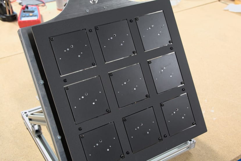
The design consists of a number of stacked plates, with nine individual heater plates that hold two resistors and a thermal cut-out (222-8224) that prevents the temperature exceeding 40°C.
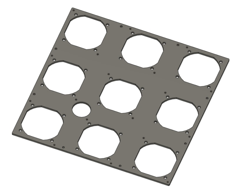
The fan plate holds nine 12V, 60mm fans (885-5088) and the heater plates are on stand-offs, with an air gap between them to allow for cooling. To reduce vibration and noise, rubber mounts (022-1030) were used to secure the fans. A final backplate connects the plate stack up to the aluminium extrusion frame and also serves to mount the control box.
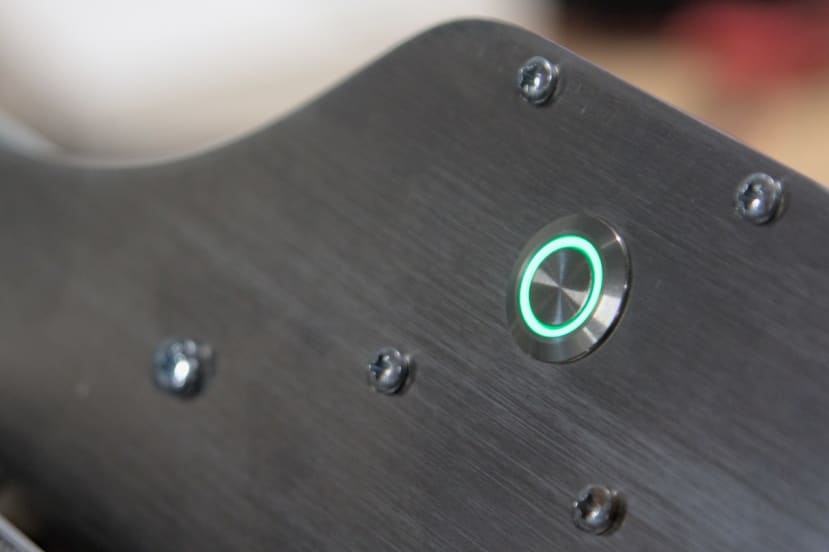
The only user interface component consists of an IP-rated push button (175-9550) that features an RGB illuminated ring which is utilised to indicate the three operational states of idle, heating and cooling.
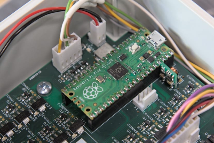
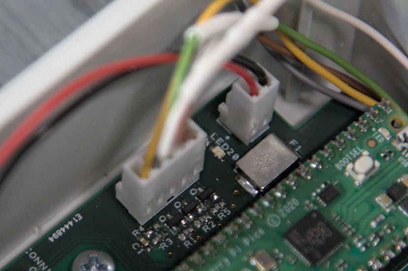
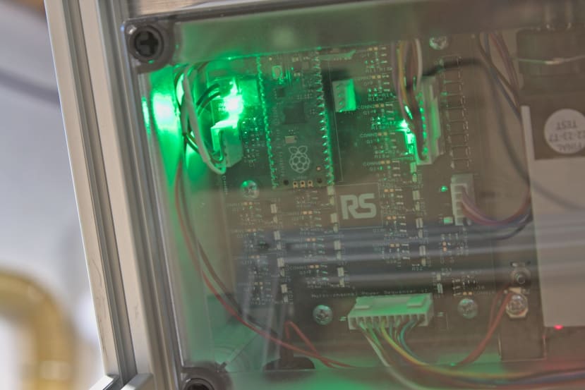
To coordinate the heating and cooling a custom control board was designed and assembled. Eighteen output channels are provided by the board and which are commanded by a Raspberry Pi Pico with control software written in MicroPython. The board is sized to fit in a relatively compact Fibox IP-rated enclosure (289-6465) that features a transparent lid, allowing the indicator lights to be viewed.
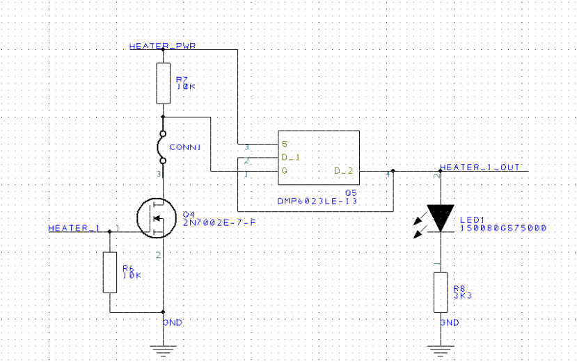
Instead of using relays to switch the fans and heaters, a high-side switch circuit that uses a P-channel MOSFET was designed. Each channel was designed to be capable of switching 2A and has a TVS diode to reduce the chance of ESD-related damage, which could potentially happen on the channels used to control the fans. Additionally, each channel features a green LED to indicate that the output is turned on.
The maximum supply current of the board is 2.5A, which is limited by a Bourns polyfuse (647-8099) on the input, and the trace widths are designed to handle a 2.5A maximum.
Demonstrator Assembly
With the design completed, we moved on to cutting the extrusion frame. To make the best use of the extrusion we had bought, an online cut calculator was used to produce a plan.
Connection cubes (052-3253) were used to join the extrusion sections for a neat appearance. These are sold as a kit that includes three self-tapping screws and plastic covers that snap into the cube itself to cover the screw heads.
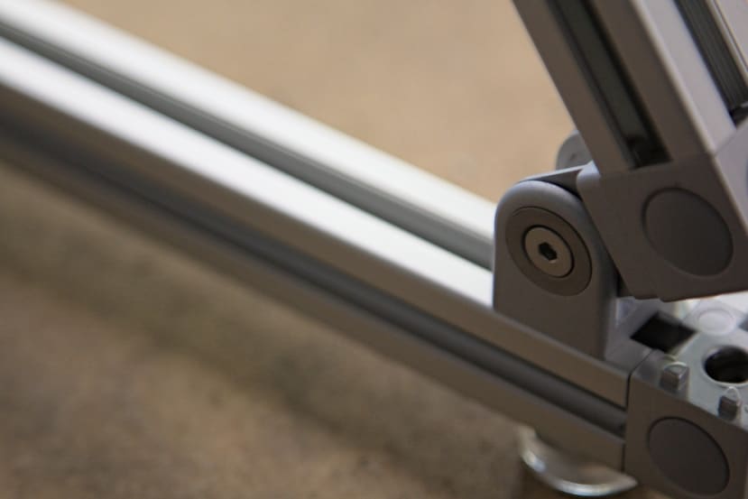
Pivot joints were utilised to allow the base plate to sit on a slight incline that would allow the bearings to “hang” on M4 screws threaded into the heating plates. These screws were not thread-locked into place to allow for adjustment to fit the various bearings
Each heater plate consists of two resistors and a thermal cutout, which made for a number of holes that needed tapping in both M2 and M3 sizes. Additionally, one M4 hole is present for the bearing mounting screw.
During testing, we found that bare aluminium was surprisingly IR reflective even with a rough, unfinished surface, which caused issues with the thermal camera seeing reflections rather than the temperature of the plate itself. To alleviate this, each plate was roughened with sandpaper prior to being painted with multiple coats of matte black paint.
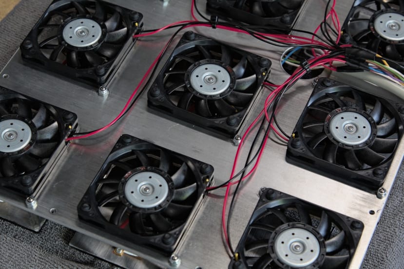
All nine fans were mounted and soldered to a section of ten-core “YY” control cable (445-1480) that terminates in a ten-pole plug (144-4192) with a matching panel-mount socket. We decided to use connectors rather than installing cable glands into the control box for ease of assembly — the plates could all be wired together as separate components and then plugged into the control box.
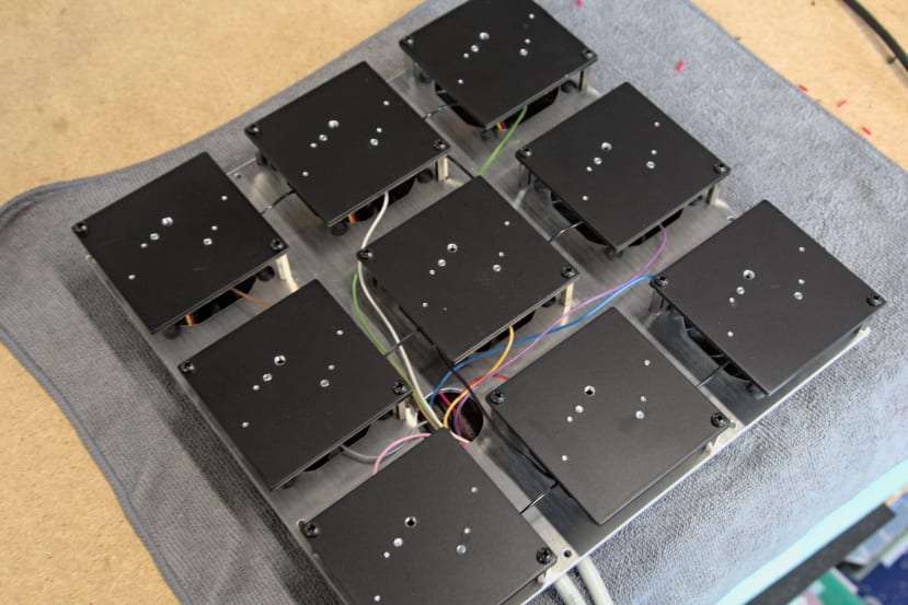
Each heater plate was then fastened to the fan plate using two 20mm stand-offs (022-1162) and a dab of thread lock to ensure nothing could vibrate loose. To secure the fan plate to the base plate, another series of stand-offs was utilised that also supported a decorative acrylic trim plate, filling the gaps between the heater plates.
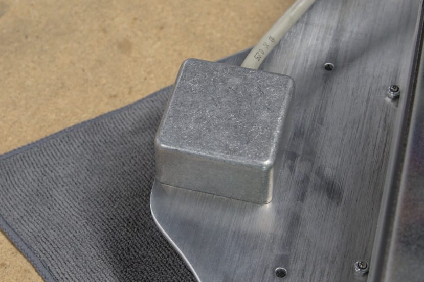
To conceal and protect the wiring for the button, a small die-cast aluminium enclosure (226-4076) was screwed in place, and a hole drilled to pass the button cable through.
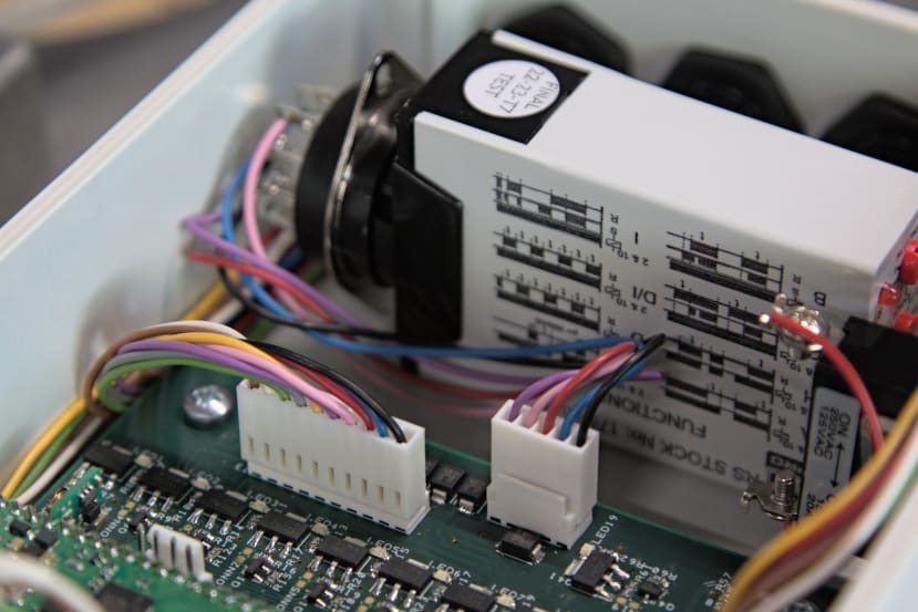
As an additional layer of guarding against the heaters becoming stuck on should the Python program crash, a multi-function timer (178-5021) was installed into the control box. The timer enable pin is triggered by an output on the control board and then engages power to the high-side heater switches on the control board. The output duration is set to be a few seconds longer than what the code turns the output on for so that the heating cycle is not prematurely terminated.
The final assembly steps consisted of screwing the control box onto the base plate, the plate stack onto the aluminium extrusion frame and then screwing into place the acrylic decorative front panel.
Power was then applied and the demonstrator tested for correct operation with a short test program that toggled the timer trigger pin and stepped through each heater and fan output.
Demonstration Video
To Finish
In this article, we’ve taken a look at the construction of a demonstrator that simulates the failure of a bearing that can be imaged using a thermal camera offered by RS Pro. Design files and example software for the multi-channel control board are available on GitHub.