SunBoard - Charge Controller with MPPT & Bluetooth | DesignSpark
Follow project
 Dave from DesignSpark
How do you feel about this article? Help us to provide better content for you.
Dave from DesignSpark
Thank you! Your feedback has been received.
Dave from DesignSpark
There was a problem submitting your feedback, please try again later.
Dave from DesignSpark
What do you think of this article?
 Photovoltaics may be the future of energy generation though it requires additional electronics to work efficiently. SauleBoard is an open-source project of a simple charge controller with an MPPT algorithm and wireless control for small solar panels.
Parts list
| Qty | Product | Part number | |
|---|---|---|---|
| 1 | LM2576T-ADJG Step-Down Switching Regulator | 463-050 | |
| 1 | Microchip ATMEGA328P-PU, 8bit AVR Microcontroller | 131-0276 | |
| 1 | STMicroelectronics 40V 3A, Schottky Diode | 687-0877 | |
| 1 | Positive Voltage Regulator 5V 1A TO220 | 7968060P | |
| 6 | HARWIN, Archer M50 Jumper Female Straight Black Jumper | 909-4382 | |
| 2 | RS PRO 4.7kΩ Carbon Film Resistor 0.25W ±5% | 707-7726 | |
| 2 | RS PRO 1kΩ Carbon Film Resistor 0.25W ±5% | 707-7666 | |
| 2 | RS PRO 10kΩ Carbon Film Resistor 0.25W ±5% | 739-7538 | |
| 1 | RS PRO 220Ω Carbon Film Resistor 0.25W ±5% | 707-7612 | |
| 2 | RS PRO 120Ω Carbon Film Resistor 0.25W ±5% | 707-7599 | |
| 1 | RS PRO 2.2kΩ Carbon Film Resistor 0.25W ±5% | 739-7483 | |
| 1 | RS PRO 12kΩ Carbon Film Resistor 0.25W ±5% | 707-7757 | |
| 6 | RS PRO, 2 Way, 1 Row, Straight Pin Header | 251-8086 | |
| 2 | RS PRO, 36 Way, 1 Row, Straight Pin Header | 251-8632 | |
| 3 | WR-TBL Terminal block - serie 102 | 826-7220 | |
| 1 | STMicroelectronics 1N5908, Uni-Directional TVS Diode, 1500W, 2-Pin DO-201 | 793-1311 | |
| 1 | Bourns 330 μH ±10% Ferrite Leaded Inductor, Max SRF:2MHz, Q:20, 600mA Idc, 760mΩ Rdc, RLB | 172-9569 | |
| 2 | RS PRO 10μF Electrolytic Capacitor 50V dc, Through Hole | 170-1245 | |
| 2 | Vishay Single Layer Ceramic Capacitor SLCC 100pF 1kV dc ±10% S3N Dielectric F Series Through Hole | 716-7135 | |
Each year renewable energy sources, with photovoltaic panels at the forefront, increase their contribution to the overall electricity production. The view of the solar installation on the roof of our neighbours is not so surprising anymore. But the way such a system works is not so widely known. The Solar charger project described below is firstly a technical challenge for a student like me but also an attempt to understand the principles of operation of the technology that is shaping the future of energy generation. What is required to charge a battery from the solar panel? How to implement a simple digitally adjusted step-down regulator? Why MPPT is crucial, especially for larger installations, and what is actually the MPPT algorithm?
A little bit of background
In September last year, I’ve started a bachelor degree in electronics at the University of Manchester. I’m from Poland, so I was excited about moving to the UK and studying the subject, which I have always been fascinated with. Unfortunately, quickly it turned out that there was no chance for any classes at the campus, so I was forced to move back to Poland and start studying remotely. I decided, however, that regardless of the situation, I will try to make the most of the theoretical content provided by the lecturers and complement this with my practical projects. And that's the origin of SunBoard.
Project definition – my approach to handling technical challenges
After the first semester and an introductory course on semiconductors, I’ve decided to try my hand out at solar energy and build a simple system comprising everything I need to generate, convert, store and use the power provided by the Sun. As a general project requirement, I’ve also decided that I will try to keep it well organised and follow the simple process that I have developed based on the Agile / Lean management approach (figure 1).

Figure 1 – Hardware development process
Apart from following a predetermined plan, I’ve also decided to use a version control system to back up all files regularly and track any changes to the design. For this, I used GitHub with their desktop app. You can find the repository with design files here.
I have started with general system requirements and pre-design research. After digging a bit in the university online library and DIY projects websites, I found a couple of great resources like:
- "Photovoltaic Power System: Modeling, Design and Control" by Weidong Xiao (University of Sydney) [this was my main source of information about Photovoltaics generally]
- "Solar MPPT Battery Charger for the Rural Electrification System” by Microchip (36 p. application note) [I have used it as an example of how such a system can be implemented]
- Other data sheets, application notes and online examples of similar projects (e.g. Arduino MPPT Solar Charge Controller)
At this point, I've also specified general system requirements such as:
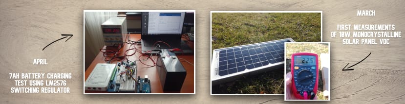
- The system will comprise of 10 W monocrystalline solar panel and 7 Ah (12 V) rechargeable sealed lead-acid battery (mainly for proof-of-concept purposes);
- The device should be able to act as a step-down converter with adjustable output voltage in the range of 13.0 – 15.0 V;
- There should be an option for sending reports on the state of the device wirelessly over Bluetooth;
- The charger needs to be able to track maximum power point (MPPT algorithm);
Even though I tried to follow an iterative approach to designing and prototyping, I also decided to set most of the requirements in a fashion, which will ensure that I won't have to change them during the project and fortunately I managed to do that.
SunBoard 1.0 - functionalities and performance of the final device
First things first, below you can find details about the final effect of my work (for now), i.e. the first version of SunBoard. Quick calibration and a series of preliminary tests showed that the device does its job quite well, maybe apart from the efficiency, which is relatively low.
Hardware development – from prototypes to custom-made PCBs
The project of the charger can be divided into two main parts: hardware and software (or rather firmware). The hardware on the other hand comprises two sections: Switching step-down regulator and MCU & Bluetooth segment.
Adjustable buck (step-down) converter
It quickly turned out that if I want to charge the battery, especially from the solar panel, the core of my hardware will be an adjustable buck converter. I have used off-the-shelf power modules in the past however, I have never tried to build one myself. I started with the intention of building a converter from scratch, based on MOSFETs and fundamental electronic components but after few attempts, I discovered that having just a fundamental knowledge of circuit analysis, it’s close to impossible for me to make it work efficiently. Hence, I decided to use an IC manufactured specifically for that purpose.
I chose LM2576-ADJ with an output voltage of 1.23 to 37 V (±4%) and a guaranteed 3.0 A output current working at the frequency of 52 kHz. It requires a couple of additional components such as electrolytic capacitors, resistors, Schottky diode and an inductor. However, the datasheet guides the user quite well throughout the component selection process.

Figure 2 - LM2576 step-down schematics
Apart from the LM2576 chip and supporting components, I’ve added a reverse current protection diode to prevent current flowing back from the battery to the solar panel, e.g. during the night. There are also two voltage dividers for measurements, a current sensor header, along with a couple of test points and jumpers (may also be used for connecting external switches).
For the buck converter to be digitally adjustable, I created a feedback loop that is connected to MCU (Microcontroller Unit) in such a way that by changing FDBK voltage output voltage can be controlled.
Microcontroller unit and Bluetooth module
While the charger is mainly the buck converter, it has to be controlled by some external subsystem. In this project, I decided to use the Atmega328P 8-bit AVR microcontroller, as I have had experience with Arduino boards in the past, often based on AVR MCUs. It has internal ADC (used for voltage measurements) and hardware and software UART serial ports (for debugging and Bluetooth communication).
For the Digital-to-analog converter, I have used an external MCP4725 DAC board with an I2C interface. I tried to create an internal onboard DAC using a PWM signal from the Atmega microcontroller alongside with operational amplifier and RC filter. Its performance was, however, not satisfactory enough to control the feedback loop of the buck converter.
PCB design and assembly
|
After about two months of prototyping (Design --> Build --> Test loop iterations) and finding the most suitable components, modules and interconnections between all of them, the time came for finalising design files. I’ve made some last changes to the schematic, ask a couple of other hobbyist/engineers for any pieces of advice online, and start creating a layout for the Printed Circuit Board (PCB). As one of the last things, I added a gold pin header connected to two unused I/O pins of Atmega328 along with +5 V & GND connections. These are marked as Dev Ports as they are dedicated for future development purposes or external devices (like ESP32 with Wi-Fi capabilities) that may be connected to the board. |
|
Figure 3 - SunBoard PCB assembly animation |
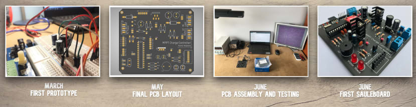
After assuring that all systems and hardware requirements should be met by the board and running the final ERC test in schematic and DRC test in board file, I exported Gerber files for manufacturing. I ordered 5 test boards from JLC PCB, as their service was inexpensive and seemed like a good fit for the first batch of test boards. Below you can find some photos of the boards, soldering components, and the first approach to connecting the charger to the power supply.
Software development – from first sketches to the board library
I didn’t have much experience with "pure" C/C++ embedded software, but I have been using the Arduino library for a long time, so I decided to stick to that option in this project as well (at least for the prototyping and first boards). I started with separate sketches for each functionality, and I tried to test them one by one before merging them into bigger files. Finally, I decided to try my hand at Object-Oriented Programming (OOP) and create a C++ library that would make the code more reliable, easy to read and edit.
There are several methods in the board class however, the two most interesting ones are get() and setVoltage(). The first one may be used to measure input and output voltage as well as the current (using Grove ACS70331 based module), while the following one is used to set the voltage at the output.
Taking voltage and current measurements
Measuring voltages, which includes also measuring current sensor output voltage is done by Atmega328 internal 10-bit ADC. The method (function in the class) takes as a parameter an int number indicating a command, however, by using defined in the library macros we can write e.g. board.get(PV_VOLTAGE).
After being called it evaluates what is to be measured and what are the adequate voltage divider resistor values (values of which have been entered during the calibration process). Then it takes 100 measurements one after another with 5 ms breaks. It then calculates and returns the average of those readings.
Setting output voltage (Proportional controller)
The method that sets the output voltage is just a bit more complex as it uses the approach of a proportional controller. After we call it by writing e.g. board.setCharging(12.54), it will try to do its best to set the output voltage to 12.54 V.
It starts with calculating the theoretical voltage that should be set on the feedback pin, and hence an adequate 12-bit value that should be passed to the DAC module. It sends it and then waits 200 ms for the output voltage to stabilise. After this time it takes a measurement (using the get method) of the true output voltage and calculates the error.
If the error is bigger than ± 15 mV the board will try (for a maximum of 5 times) to decrease the error value. It firstly divides it by two, and then add/subtract it to the originally expected value. After first calibration and tests, it seems to work pretty well, as the algorithm was able to size down the error so far in all attempts, always with less than 5 iterations.
/* Method that changes the charging voltage (LM2576 Vout) to a given value  */
void Solar_charger::setCharging(float Voltage_V) {
  Adafruit_MCP4725 MCP4725_DAC; // Create MCP4725_DAC object
  MCP4725_DAC.begin(0x60);      // MCP4725 digital DAC I2C configuration (Adress: 0x60)

  /* Start by setting the feedback (and hence the output) according to the theoretically calculated fdbk value */
  uint16_t Vbat_desired_mV = (1000.0 * Voltage_V), Vfdbk_MC4725_mV, fdbk_MC4725;
  uint16_t error, Vbat_desired_mV_corrected = Vbat_desired_mV;

  Vfdbk_MC4725_mV = (1309 - (uint16_t) ((float) Vbat_desired_mV * 0.05988)); // Calculate theoretical value of fdbk in mV
  fdbk_MC4725 = map(Vfdbk_MC4725_mV, 0, Vin_mV, 0, 4095);      // Map the value to 12 bit int (12-bit  resolution: values between 0 - 4095)
  MCP4725_DAC.setVoltage(fdbk_MC4725, false);                  // Send the value to the MCP4725 digital DAC

  delay(500);                                                  // Wait for the voltage to stabilise
  error = Vbat_desired_mV - Solar_charger::get(BAT_VOLTAGE);   // Calculate the error

  for(uint8_t i = 0; i < 5 && MOD(error) > 15; i++) {          // For error > 15 mV minimise it using "proportional controller" [Max 5 itterations]
    Vbat_desired_mV_corrected += (error / 2);                  // Add/subtract half of the error to Vbat desired
    if(Vbat_desired_mV_corrected > 6000) {                     // Protect the board from seting the voltage below 6 V and cutting off MCU power
      Vfdbk_MC4725_mV = (1309 - (uint16_t) ((float) Vbat_desired_mV_corrected * 0.05988)); // Calculate theoretical value of fdbk in mV
      fdbk_MC4725 = map(Vfdbk_MC4725_mV, 0, Vin_mV, 0, 4095);
      MCP4725_DAC.setVoltage(fdbk_MC4725, false);
    }
    delay(500);                                                // Wait for the voltage to stabilise
    error = Vbat_desired_mV - Solar_charger::get(BAT_VOLTAGE); // Calculate the current error
  }
}
MPPT algorithm
MPPT algorithm is one of the cores of the SunBoard. The need for any algorithm at all arise from the specific behaviour of solar cells. Their I-V characteristic is not linear like e.g. an ideal resistor, but it's rather a curve that looks like the one shown on the left. You can notice that the voltage is constant and independent of the current up to some point, after which it plummets and quickly reaches the x-axis, i.e. 0 V.
Figure 4 - Solar cell I-V and P-V characteristics (source: "Photovoltaic Power System: Modeling, Design and Control") |
The second important graph is P-V characteristics, which illustrates Power (Solar cell current * voltage) against cell voltage. Now it becomes obvious that the power delivered by the photovoltaic panel depends on the voltage/current - the load connected to the panel. So depending on the impedance of the load there will be different voltage, current and hence power generated. Even if the Sun is at its zenith, there are no clouds nor wind, but we will connect a large value resistor to the panel, we will get only a fraction of the max panel power. The same is true for batteries. That's why it's often cost-effective to implement MPPT charge controllers that will alter the input conditions in such a way that the solar panel will be working at its maximum power point at all time. ...And that's where the name comes from, as MPPT stands for Maximum Power Point Tracking. :-) |
There are several ways to implement such an algorithm, from the easiest ones up to much more complex ones, that can operate fast and with great precision, which can be crucial e.g. at the large solar farm generating Mega Watts of power.

MPPT Algorithm tests with 10 W photovoltaic panel
The easiest to implement is the "hill-climbing" algorithm, which is an optimization technique. The idea is to alter a variable that changes the input (PV panel) condition (that can be a duty cycle in a switching step-down regulator) and check if the power delivered to the system is greater or smaller than the one before the change. This approach can easily track down the Maximum Power Point (MPP), however, as always, it can't be so simple. In fact, there are several major disadvantages of such an approach. One of them is the fact that after each change in the input condition the board has to give some time PV panel and charger to stabilise - because of this "hill-climbing" strategy may be a bit slow and unable to quickly react to changes. The other significant problem is the oscillation around MPP. The charger will never reach a steady state as it will always try to go "down" or "up" the hill.
Nevertheless, it seems that the "hill-climbing" approach is a good choice for the beginning and for many applications it will "do the job" well. If it comes to the SunBoard, I've just started experimenting with the MPPT algorithms as the software is still in the development process. However, I hope that in the next few weeks I will be able to release at GitHub the final version (at least for now of course).
Conclusion and future development plans
|
When I started the project in February I thought that making the simplest photovoltaic system: PV Panel - Charger - Battery, with DIY electronics can't be too difficult. How wrong I was. :-) It turned out that with my fundamental knowledge of electronics, some experience with Arduino and virtually no experience with solar panels, all the hard work was ahead of me. Nevertheless, it was and is (as the project is still under development) a great experience and a solid amount of new knowledge in the field of PV, electronic system design and system/device design as a whole. If it comes to future development plans, I will for sure firstly try to end general system tests with PV panel, charger and battery working for a week or two, just to see if there are any changes that can be made to the code or electronics before installing the Board in my shed, that urgently needs some independent lighting system. I'm also trying my hand at RTOS and ESP32 development boards, so maybe I will consider making SunBoard an IoT device so that the control can be actually remote (which might be helpful during holidays, when there are times when nobody is at home). As the project is still under development, I will be very grateful for any advice, thoughts or other feedback on the SunBoard project. I'm also happy to answer any questions that will appear in the comments. |
Tests of my Arduino based rover |

Finally, thank you very much for making it to the end of this article!
Karol