Multifunctional Robot For Competition Challenge
Follow article Dave from DesignSpark
How do you feel about this article? Help us to provide better content for you.
Dave from DesignSpark
Thank you! Your feedback has been received.
Dave from DesignSpark
There was a problem submitting your feedback, please try again later.
Dave from DesignSpark
What do you think of this article?
Robot design is a complete task that involves many different skills that include electronics, mechanical design and programming as well as planning, working in groups and problem-solving. This is a common project used in many courses to evaluate students’ capacities and is sometimes associated with a competition that motivates the students to improve the performance of their robots.
In this article, we are going to explain how we can make a multifunctional robot which was able to complete 4 different tasks:
- Fight against other robots in a SUMO-type fight. This task must be completed in an autonomous way.
- Complete a maze, also in an autonomous way
- In a grid, the robot must go from one point to another in an autonomous way. We can only give him instructions once because, when the robot starts to move, we are unable to send more information to him.
- The robot is also Remote Controlled, which permits one to complete many different tasks, such as moving a piece of wood from one point to another, drawing lines by attaching a pen to the chassis or playing bowling by pushing a ball.
The project covered in this article was created as a capstone project for the MSc. in Electrical and Electronic Engineering program at the Public University of Navarre in Spain's third course on printed circuit board (PCB) design.
There are some limitations to be accomplished for this project in order to guarantee fair competition and evaluation of the projects:
- MAX SIZE: 10x10 cm without height limitation.
- MAX WEIGHT: 500g.
- MAX BUDGET: 50 €
- Must have a START button
- In sumo mode, the robot must wait 5 seconds before it starts to move.
- POWER SOURCE: 3.7V,650mAh batteries (we will use 2 of them).
- CONTROL: 8-bit PIC microcontroller.
- MOTION: DC motors.
In order to explain the project more clearly, we will separate it into three different parts that will address the electrical design (part 1), mechanical design (part 2) and programming (part 3):
1. Electrical design
Taking into account the limitations of this challenge, we will describe the circuits and sensors we used in the robot in order to accomplish the different tasks.
Microcontroller:
This is probably the most important part of the project. For this project, we selected the PIC16F886 as our micro. We will explain more of it in the programming part.
A modular connector is required to link the PC and the microcontroller and enable direct robot programming and debugging. The illustration below explains how the modular connector connects to the PCB and the microcontroller.

Figure 1 Connection of the RJ12
Linear voltage regulator:
This component allows us to reduce the voltage to 5V so we can supply all components (except motors). We use the LM7805 with some capacitors to guarantee its operation (see Figure 2).
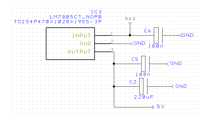
Figure 2 LM7805 connection
Close range infrared sensors (CNY70):
We will use 3 of them, in the mechanical part, we will look at the position of these. The CNY70 is used to detect the white line delimiting the sumo arena and the grid in a similar manner to a line follower.

Figure 3 Connection of CNY70
As can be seen in Figure 4, the sensor will need to be powered at 5 V on pins 1 and 3, and connected to GND through a series of resistors on its remaining pins. The value of these resistors will be R=220 for pin 2 and R=10k for pin 4. From the latter, the logic information provided by the sensor will be sent to the PIC.

Figure 4 Connection of CNY70 in DesignSpark
Long-ranged infrared sensor (GP2Y0A21YK):
The long-range infrared sensor will be used to identify the elements in its environment, whether they are the walls of the labyrinth or another robot. This element has an analog output, so it will be necessary to connect it to a pin of the microcontroller capable of reading this type of information. The problem with this sensor is that it doesn’t have a linear output as it is shown in the graph below:

Figure 5 Analog response of the long-range infrared sensor
According to the graph above, it can be seen that for distances smaller than 10cm the same value is obtained as for certain distances larger than 10cm. We will solve the way to solve this problem in the mechanical part section. This sensor only needs a 5V and GND connection so there is no need for an additional conditioning circuitry and it can be directly connected to the microcontroller analog to digital conversion input.
Motor drivers (L293D):
Instead of 5V, we give them Vcc (6V) to acquire greater current values and speed up the robot. Additionally, we installed bulk capacitors at the driver's entrance that will serve as a "little battery" in the event that a voltage drop happens. The motor driver connections circuit is represented in Figure 6.

Figure 6 Connection of L293D in DesignSpark
Bluetooth module (HC-06):
Bluetooth module has 4 pines as it is described below:
- Vcc: Supply pin, must be between 3,3 and 6 V.
- GND: Ground.
- TX: data transmission pin, connected to RX PIC pin.
- RX: data reception pin, connected to TX PIC pin.
To attach the Bluetooth module to the rest of the circuit, it will be necessary to locate the RX and TX pins of the PIC, which will be pins 18 and 17 respectively. The input voltage at the receiving end of the Bluetooth module(RX) is 3.3 V so it will be necessary to add a voltage divider to the output of the PIC (working at 5 V) in order to prevent malfunctioning. Doing the maths, the value of the resistors must be R1=1k and R2=2k. (see Figure 7).

Figure 7 Connection between Pic and Module Bluetooth
LEDs:
Two LEDs are used to show the configuration that has been selected for the performance of the tests, as well as to carry out the 5-second count before the start of each test. The led control circuit is shown in Figure 8.

Figure 8 LEDs Circuit in DesignSpark
Buzzer:
It will be used as a horn when the device is remotely controlled using the Bluetooth module and it will be activated as a celebration sound when the tests are fulfilled. The buzzer control circuit is represented in Figure 9.

Figure 9 Circuit of the Buzzer in DesignSpark
Switches:
We use 2 types of switches:
- 4 mode Switch: used to choose the robot's mode and settings (see Figure 10).
- 2 mode Switch: ON/OFF switch (see Figure 11).


Figure 10 4 Mode Switch in DesignSpark Figure 11 2 Mode Switch in DesignSpark
With the latter, all the components and circuits associated with the peripherals to be integrated on the printed circuit board PCB have been described, which results in the connections with the PIC microcontroller represented in Figure 12:

Figure 12 PIC16F886 connections circuit with peripherals in DesignSpark
Table 1: Association of PIC microcontroller pins with different peripherals
PIN |
ELEMENT |
PIN |
ELEMENT |
PIN |
ELEMENT |
PIN |
ELEMENT |
|---|---|---|---|---|---|---|---|
|
1 |
RJ12_1 |
8 |
GND |
15 |
LED2 |
22 |
4Posiciones 2 |
|
2 |
Infrarrojos I |
9 |
Motor 1_1 |
16 |
LED1 |
23 |
4Posiciones 1 |
|
3 |
Infrarrojos D |
10 |
Zumbador |
17 |
Bluetooth TX |
24 |
RJ12_6 |
|
4 |
Infrarrojos C |
11 |
Motor 2_1 |
18 |
Bluetooth RX |
25 |
4Posiciones 0 |
|
5 |
Infrarrojos LARGO |
12 |
Motor 2_2 |
19 |
GND |
26 |
Switch |
|
6 |
Empty |
13 |
Motor1_2 |
20 |
5V |
27 |
RJ12_5 |
|
7 |
Empty |
14 |
Empty |
21 |
4Posiciones4 |
28 |
RJ12_4 |
2. Mechanical Design.
The stl archive that is uploaded at the end of this article contains the 3D model of the robot ready to be 3D printed in you want to reproduce this design. We will use viewpoints from this file to show the location of the different parts in order to illustrate and facilitate the construction of the robot for the users.
General views:


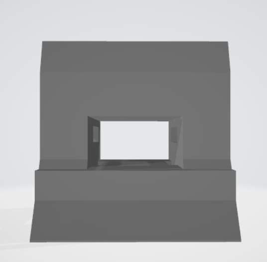


Figure 13 Top (top left), lateral (top center), front (top right), bottom (bottom left) and rear (bottom right) views of the chassis
PCB:
The PCB will be positioned at the top of the structure, fixed with screws and raised slightly with some covers to be able to pass the cables through the holes (see Figure 14).

Figure 14 PCB on top of the robot
Long-range infrared:
As was mentioned earlier, we need to do something with this sensor to "remove" the measurements between 0 and 10 cm. The solution is simple. We will put the sensor at the back of the robot in the middle hole, so if a wall is right in front of the robot, for us it will be 0 cm, but for the robot, it will be 10 cm. It is also important to take this into account for the programming part.

Figure 15 Long-range infrared position
Short-range infrared sensors:
The three short-range infrared sensors are positioned at the front bottom holes of the structure (see Figure 13 bottom left), pointing to the floor. For its proper functioning, they must be raised above the ground a few mm. Otherwise, no reflection will be received from the floor.
Batteries and dc motors:
As it is shown in Figure 15, the motors are placed at the bottom hole while the batteries are positioned at the top hole. The motors are also fixed with screws to the case in order to assure a proper fixation.
3. Programming
For the microcontroller, we used PIC16F877A. The main reason for this election is that it has enough pin count, including the serial mode connection for Bluetooth, and it also has an internal oscillator and the possibility to set the oscillation frequency at 8MHz.
The MPLAB environment and the ICD3 depuration tool were used in its programming. The program is written in C++. At the end of the article, there is a file called "Code" that contains the main code.
For Bluetooth, any application of Bluetooth controller for mobile can be used. We chose “Bluetooth electronics” for the factory and “Bluetooth Automation” for the grid. These two can be easily found on the Google Play Store. For the factory, we needed 5 buttons, 4 for the movement and 1 for the horn. It’s important to configure each buttons with these letters:
- Forward: a
- Backward: b
- Left: d
- Right: i
- Horn: k
For the grid, it's important to understand the logic of the programming: odd-numbered commands will tell the robot how many intersections it has to go forward until it has to turn. Likewise, paired-numbered commands will tell the robot if the turn is to the right or to the left, and, to finish indicating the path, we will have a start button. With an example, it will be better understood. Let's say I want to go from C to 4 (see Figure 16). Then I would have to press the following sequence of buttons:
4-Right-2-Start

Figure 16 Grid example. In Red the path to achieve
After understanding the logic of the programme, we will see the interface that will be used for the grid and its configuration.

Figure 17 Interface for grid
The figure below shows the characters we must assign to each button:

Figure 18 Interface for grid. In red, the character to assign at each button
Conclusions
Finally, we will explain a little about how to switch on the robot and select the mode. To turn it on, first, we will have to choose the mode to be used, this is selected with the 4-position button: The first one is for sumo, the second for the labyrinth, the third for the factory and the last one for grid. Once selected, we will only have to press the 2 positions button and, after 5 seconds, the robot will turn on with the test configuration.
This project has been pretty difficult but, at the same time, the one we have learned the most. I sincerely hope you enjoyed reading this article and that it inspired you to build the robot. Here, I'll leave you with a video showing our robot working his way through all the challenges he faced.