Mindful Droid - Bringing Awareness and Change to Air Pollution Levels: Part 2
Follow article
 Dave from DesignSpark
How do you feel about this article? Help us to provide better content for you.
Dave from DesignSpark
Thank you! Your feedback has been received.
Dave from DesignSpark
There was a problem submitting your feedback, please try again later.
Dave from DesignSpark
What do you think of this article?
Mindful Droid 2.0 - Build Guide
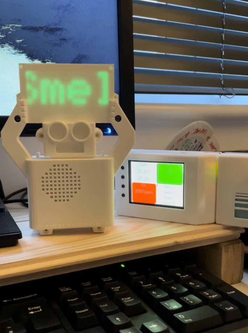
The Mindful Droid is a pollution awareness device. The digital alerting robot has a passive way of encouraging activism amongst school children on their school commutes and also brings visual awareness warnings about the effects of Air Pollution and how to prevent it.
With the assembly of the ESDK, a device that detects Air quality using the PM2.5, VOC, and CO2 sensor, the Droid will be able to read the Air Quality data from it, bringing forth visual awareness of this data in an understandable form to users.
The Droid also have the ability to monitor data outdoor, giving appropriate warning signs based on the environment it's in. In this case, it will be during “to and from” school commutes.
The Build for the Mindful Droid was following the design principle of simplicity and being thorough to the last detail. Hence, the approach of constant refining ensures the ease for others to assemble and operate.
Moving on from part 1 of my article, the next phase was getting the PCB board design made and ordered, with other materials for the build-in place for construction.
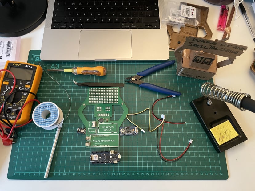
PCB Design and Electronic Part List
- PCB Board Design
- Arduino, MKR WIFI 1010 - 176-3647
- Seeed Studio Air Quality Sensor v1.3 Grove System, Indoor Air Quality Testing
- MQ-7 Gas Sensor (Carbon Monoxide) × 1
- High Capacity Lithium-Ion Battery Pack (6700mAh) × 1
- JST PH 2-Pin Cable - Female to Female Connector 150mm × 2 ( If not available splice two females together)
- HARWIN M20, 2.54mm Pitch, 36 Way, 1 Row, Right Angle Pin Header, Through Hole
- RS PRO M3 x 6mm Hex Socket Cap Screw Plain Stainless Steel
- RS PRO, M3 Brass Threaded Insert diameter 4mm Depth 4.78mm
- RS PRO, Pozidrive Countersunk Stainless Steel Machine Screw M2 x 5mm
Tools
- Wires for PCB wiring (should come with the sensors)
- Double-sided adhesive tape
- Soldering Iron, Solder etc
- Glue gun
- Scalpel Knives
- Tweezers
- Wire Cutters/Pliers
- Vernier Callipers
- Hand drill
- Dremel / Hand File
PCB Board Part List
| Comment | Value | Description | Designator | Footprint | Quantity | Part # |
|---|---|---|---|---|---|---|
| BUZZER | 8.5mm 3.3mm Externally Driven 8.5mm 80dB@5V,10cm 2.5V~4.5V | B1 | BUZZER - 8.5mm 3.3mm | 1 | C94599 | |
| BAT-CON | BAT1, BAT2 | LIPO BAT-CON | 2 | C47647 | ||
| Cap | 0.1uF | Capacitor | C1 | 0603 cap | 1 | C519438 |
| Cap | 100uF | Capacitor | C2, C3, C4 | 1206 CAP | 3 | C312983 |
| Diode General purpose | Default Diode (IN4007) | D1 | SOD123 | 1 | C181127 | |
| mmbt2222a | NPN General Purpose Amplifier | Q1 | SOT23 | 1 | C181121 | |
| Res | 100 | Resistor | R1 | 0603 res | 1 | C22775 |
| Res | 10K | Resistor | R2, R3, R4 | 0603 res | 3 | C25804 |
| Push-button | Push-button (C3318895) | S1, S2 | PUSH BUTTON-3x4.65mm | 2 | C318895 | |
| MKR WIFI 1010 | U1 | MKR WIFI 1010 | 1 | |||
| GROVE AIR QUALITY CON | U2 | 4 PIN SMD CONNECTOR | 1 | C541776 | ||
| MICS5524 | U3 | MICS5524 | 1 | |||
| A-LED | WS2812B Addressable led | U4, U5, U6, U7, U8, U9 | WS2812B-2020 | 212 | C965555 |
NOTE
If this is new to you as it was me, it would be best to have the PCB board designed and the main components attached directly from the PCB makers. I will be sharing the files needed to order the PCB board and link for manufacturers. However, if you are quite familiar with this, the part list above will help to build the PCB board.
Build and Assembly Phase
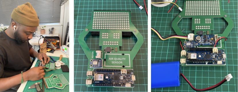
The build for this project has been a huge learning process for me, and as a Design Engineer, you would expect me to know a lot more, but that wasn’t the case. On this project, I learned how to solder for the first time (unbelievable, I know) and some other new discoveries.
Also as expected, I had some challenges with this project. Some of these were: a sensor not providing appropriate results, having to desolder the sensor and trying to make it right with a different sensor component, learning to code and also dealing with practical design issues for the Droid enclosure fixtures.
This project wouldn’t have been possible without the help and guidance of a Wiz friend, who is also a part of the DesignSpark influencers Ahmed Oyenuga - Ahmsville. Please do check out his awesome project and progress.
Components on PCB Board
I started by soldering the Arduino board to the PCB board, placing the pins through the holes and soldering on the PCB board rear and also did the same with the sensor using header pins. Being my first time soldering I had to ensure I got the right temperature to heat up the solder of about 350 degrees and also ensure I don’t have solder bridging across the pins.
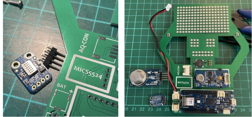
I did mention I had issues with a sensor not giving accurate results and that was the MICS5524 gas breakout sensor, which I haven’t added to the part list, although it's on the PCB board. I have had to change it to an MQ-7 Gas Sensor which I am hoping will give the desired CO outdoor readings. My finished article will address and resolve to join the new CO sensor to the PCB board.
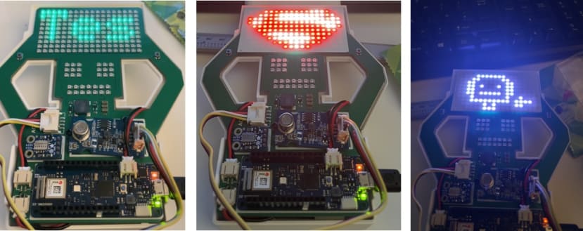
Once this was sorted the next phase was to test out the RGB addressable LEDs, soldered components and check for connectivity. Below is a short video I made during the testing of the Mindful Droid, where myself and Ahmed got a little bit excited with the testing result.
Here are some further examples of the possible outcome we can have with the addressable LEDs.
With the LEDs working as intended, the focus is now on how to fit all of this into an enclosure that is compact and robust for indoor and outdoor commute, as well as adhering to childrens' usage.
The pictures below show the ongoing stage for the enclosure which has been quite a challenge. I tried to find a solution to fasten the two enclosures together whilst trying to conserve space. My last resort was to possibly make it bigger which I wasn't willing to do. I did try lip groove on edges and snap hook features which failed and snapped in the process, costing time and multiple failed prints.
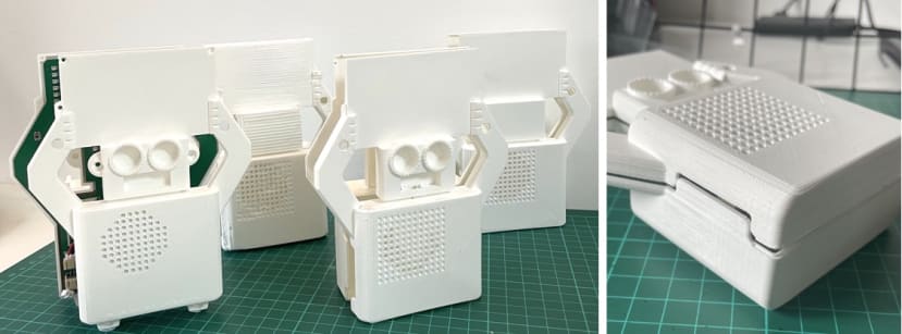
With much perseverance, I came up with a solution of including additional body parts which were ears and feet to the Droid that will serve as fastening support for tiny but durable screws to fit on as seen below.
The final Article will have further amendments with the new CO sensor. There will be in-depth detail for assembly, real-time testing and data gathering with connection to the cloud, coding and how the LED pixel art display has been generated using open source programs.
CAD files and schematics will also be updated in the Final Article.