Interfacing a 1967 Paper Tape Reader: Part 5
Follow article
 Dave from DesignSpark
How do you feel about this article? Help us to provide better content for you.
Dave from DesignSpark
Thank you! Your feedback has been received.
Dave from DesignSpark
There was a problem submitting your feedback, please try again later.
Dave from DesignSpark
What do you think of this article?
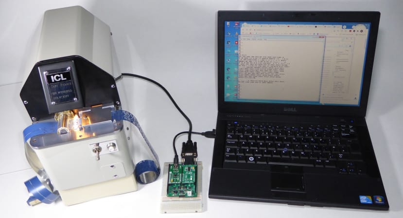
The finished interface sits in its box supporting the heavy weight of the Elliott TRM250 reader. The ‘host’ computer is my trusty MikroElektronika dsPIC33 Clicker 2 programmed in Forth; a laptop merely performing the function of a dumb terminal in this case. The blue tape is Mylar tape: it’s far more robust than paper and was used for master tapes. The snag was that it knackered punch pins and wore through tape guides if used routinely.
Previous articles in this series
Part 1: Introduction to paper tape and the Elliott TRM250 tape reader.
Part 2: Designing an ‘MCU friendly’ interface.
Part 3: Updated solenoid driver design and the MCU circuit.
Part 4: Boxing up, power supplies and testing.
In this final part, I’ll be discussing the PIC24 firmware, the addition of an RS-232 buffer module to link the reader to a host, and how paper tape was used for program and data storage.
The Interface Firmware
Compared to pre-microprocessor days, getting an electronic computer to talk to a clunky piece of machinery like a paper tape reader is a relatively simple task, thanks to the microcontroller chip. Look upon the MCU as a kind of translator: it converts the PTR’s ‘language’ of electrical signals to that of the host computer. And vice versa. This used to be achieved with boardsful of transistors or later on, TTL logic chips. In 1976 General Instruments launched the Peripheral Interface Controller (PIC) chip to support their new 16-bit microprocessor – the CP1600. The MPU was a flop, but a spin-off company called Arizona Microchip marketed the PIC as a microcontroller, and the rest is history. So, I’m using a PIC chip in the role for which it was originally designed!
As long as all the necessary signal connections have been made to the interface MCU, with any input voltage-level changing or current-driver output hardware installed, then the actual translation is performed by easily modified (debugged) program code. Before jumping straight into coding, it’s a good idea to list all the tasks that the interface must perform:
- Check that the PTR is ready: Panel switch is ON ensuring the motor is running and lamp lit, Tape-Out switch indicates a tape is loaded, and the manual RUN OUT button is not pressed. RUN OUT, while pressed, ‘fast-forwards’ the tape without reading it.
- Monitor the serial input for single-character commands from the host. Act upon those commands. For example, to start and stop the tape.
- Capture characters from the tape at a rate of 250/sec, and send them to the host via a serial link at 9600baud.
- Enable when required, a Stop-on-Character facility (see below).
The first three items are fairly straight-forward, but Stop-on-Character might require further explanation.
Stop-on-Character
The interface may be commanded to stop the tape running when a particular character has been detected and sent to the host. The key requirement is that the tape must stop moving while the character is illuminated and before the next sprocket hole is reached. This means that when the tape is started running again, no subsequent characters are missed. That’s what the friction brake is for – to kill the tape momentum when the clutch disengages. This passive brake is adequate for this PTR’s speed, but faster machines have an active, solenoid-driven brake that grips hard when needed, but backs-off when the clutch is engaged.
The character most often used to stop the tape is, you might have guessed, <newline>, ASCII code 13. SoC provides a kind of high-level flow control when, for example, a compiler reads a line of source code into a buffer before parsing it. The old computers were slow and couldn’t complete parsing the buffer before the first character of the next line arrived. Hence the PTR stopped the tape as soon as it had sent a newline character. In my case, when the host is ready for the next line, it sends the ASCII code for ‘r’ back to the interface which responds by restarting the PTR. You might think that an MCU like the 70MIPS dsPIC33E on my ForthdsPIC Clicker 2 board wouldn’t need such a facility. Well…it does when compiling source code coming in on a COM port at 38400baud. Fortunately, the terminal emulator TeraTerm can insert a delay in transmission after a newline is sent. Admittedly, it probably could cope with the PTR interface speed of 9600baud.
Firmware Structure
A flowchart for the firmware (Fig.1) shows it to be interrupt-driven: when the tape is in motion, the leading edge of a sprocket hole causes an interrupt of the main program whereupon the service routine reads the state of the data channels via bits 8 to 15 of Port B. Meanwhile, the main program has been looping around monitoring PTR switch states and checking for host commands while waiting for the Data Available flag (the output latch of Port A bit 4) to be set by an interrupt. Port A4 also drives an LED so providing some visual feedback of program operation. It’s important to realise that the interrupt is rising-edge triggered: the sprocket photosensor has to go dark before another valid trigger can occur. The combination of the narrow photosensor mask and Schmitt trigger amplifier ensures nice crisp, noise-free pulse edges are delivered to the MCU’s INT0 pin. The fully-annotated PIC24 assembler source file is available from the Downloads section below.

Host Communication
For initial testing of the interface, I used a UART-USB bridge cable (767-6200) to connect it directly to my laptop and the TeraTerm terminal emulator. Having got all the bugs out, the time came to install the ‘proper’ RS-232 serial hardware. I used a couple of ready-made modules: a MikroElektronika RS-232 Click module (823-1895) for the Clicker 2 host and a Digilent Pmod (134-6444) for the interface (Fig.2).
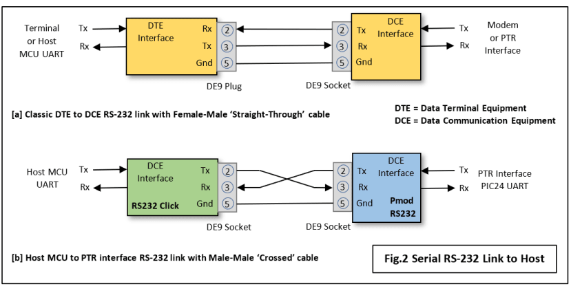
With this minimalist 3-wire configuration and no handshaking, setting up an RS-232 link couldn’t be easier, could it? I discussed the basics of RS-232 communication in this article, but it’s the terminology and acronyms used in the original standard that can cause confusion. The confusion arises because that standard defined a link between Data Terminal Equipment (DTE) – usually a keyboard-teleprinter – and Data Communication Equipment (DCE) – usually a modem. It was not specified for any kind of computer communication. So, for a computer to peripheral unit link, which end is DTE and which DCE? Do I need a ‘straight-through’ or a ‘crossed’ cable? Fig.2a illustrates the classic communication link between a DTE and a DCE. You can see that the DCE connector is wired with the Tx, Rx pins swapped over compared to the DTE. That’s perfectly logical as you would expect the Tx pin at one end of the link to be connected to the Rx pin at the other end. If that convention is followed, then the cable is ‘straight-through’: pin 2 linked to pin 2, pin 3 to pin 3. This arrangement would have been fine had an RS-232 Click module with DTE format been available. It wasn’t, so I had to use their DCE module instead, hence the male-male crossover cable (Fig.2b).

The finished interface inside the case and fully wired up. Note the 0V ‘busbar’ linking the four PSU barrel-sockets together and to the Earth pin of the mains input socket. The Earth wire from the reader is also soldered to this pin. All the tiny blue components are 0.1μF decoupling capacitors for the +3.3Vdc supply rail.


Some accessories are needed for working with paper tape storage. [1] Full 1000ft. reels of blank 1in. paper tape. [2] High-speed tape winder. Electric ones were also available. [3] Self-adhesive tape repair patches for those occasions when a knot in the tape goes unnoticed when winding. [4] A tape splicer and hand-punch set – really an ornament for the chief programmer’s desk. This one with its ICL badge probably came with a new computer installation. [5] A hand-punch for normal use. Unlike [4], this one can punch sprocket holes. Both were used for minor edits only, usually deletion (see below). One key item missing is the punch unit that produced the tapes themselves!
Working with paper tape
I can best provide a ‘flavour’ of operating a small desk-sized computer such as the Elliott 903 with paper tape as the only medium for mass storage, by describing a familiar task: editing a text file. Think how you would do this on your modern laptop using Microsoft Word or Notepad. Now read on:
- Create the initial file tape on an off-line keyboard-teleprinter with a tape punch unit. In the 1970s this would have invariably been an ASR33 Teletype. In the 1950s/60s a British computer would most likely have had a Creed 75. If you made a mistake by pressing the wrong key, you marked the offending character on the tape with a pen and then typed the correct character. Later, you went through the tape ‘deleting’ the errors. The process of deleting involved using the hand punch to convert its code to ‘all-holes’. When the computer reads the tape, codes FFh (Deletes) and 00h (Blanks) were ignored.
- If the tape contained source code for a program, it could then be compiled, with the inevitable list of errors printed out. Correcting the errors in the source tape was a pretty laborious process. First of all, a ‘Steering Tape’ had to be created on the off-line teletype. This was contained a series of commands telling an editor program called BOWDLER where corrections in the source tape were to be made.
- BOWDLER, an executable binary file, also on tape, was loaded into the computer program memory. When run, the editor read the steering code into memory.
- Now the editor paused and waited for the operator to signal that the original source tape was in the reader and the tape punch was on and loaded with enough blank tape.
- When triggered, BOWDLER went through the source tape line by line, locating and ‘correcting’ each error as it came to it. What it actually did was to make a new source tape taking into account the changes required by the steering data held in memory. The old source tape was then scrapped.
Editing was a long and laborious process with both the original tape with its errors and the steering tape being consigned to the waste bin. Needless to say, programmers spent a lot more time trying to get it right first time than they do today.
Of course, I’ve just described a successful editing session. Things frequently went wrong: paper tape is fragile, and computers were somewhat unreliable, especially the mechanical bits. Car drivers can experience Road-Rage; back then, computer operators were subject to ‘Code-Rage’. For example, when a punch unit gets glitched and puts out gibberish over the last few feet of a 500ft. tape. Or runs out of blank tape at the same point. Even if the new tape run looks good, there’s still room for operator error: there remains the task of winding the loose pile of tape on the floor into a nice neat reel. Crank the winder handle too quickly, or fail to notice a knot in the tape and suddenly you have a large supply of confetti for numerous weddings…. That’s why early computers were cased in armour-plate; their designers knew all about code-rage.
Terminal
Well, that just about wraps it up. It’s been great fun putting it all together and really satisfying to see the old machine fully operational again. Of course, I’m not going to throw away my hard-disk drives any time soon – the purpose of the exercise was to show how legacy electro-mechanical systems can be given the benefits of digital control and monitoring. This may mean that expensive machinery could be adapted to bring it into the world of Industry 4.0, so avoiding the waste of scrapping everything and starting again. The TRM250 is also an example of equipment built to last with its bullet-proof construction and easy access for maintenance and repair. Many will say it was ‘over-engineered’. That may be true, but in a world running short of resources, we surely can’t continue treating complex equipment as consumable, with built-in obsolescence a key design feature, rather than sustainability.
Now, where’s that Creed 75 keyboard-teleprinter I’ve been meaning to set up as a computer terminal for so long…..
If you're stuck for something to do, follow my posts on Twitter. I link to interesting articles on new electronics and related technologies, retweeting posts I spot about robots, space exploration and other issues. To see my back catalogue of recent DesignSpark blog posts type “billsblog” into the Search box above.