How to make a wiring loom for a Formula Student Car
Follow article
 Dave from DesignSpark
How do you feel about this article? Help us to provide better content for you.
Dave from DesignSpark
Thank you! Your feedback has been received.
Dave from DesignSpark
There was a problem submitting your feedback, please try again later.
Dave from DesignSpark
What do you think of this article?
One of the major upgrades to the University of the West of England's 2021 car was the addition of a custom ECU. This required a complete rebuild of the wiring loom which, for a low budget team, was made possible thanks to the support of RS Components. With this support, we managed our best overall finish (6th), came 3rd in our class, and won the skid pad event.
This article lays out the process we followed to create our wiring loom: design, manufacturing, and testing.
Design
Our very first step was to develop a test loom, where we could figure out what was needed to get the engine running correctly. This doesn't need to take into account of correct wire lengths, as the focus is on how everything is connected.
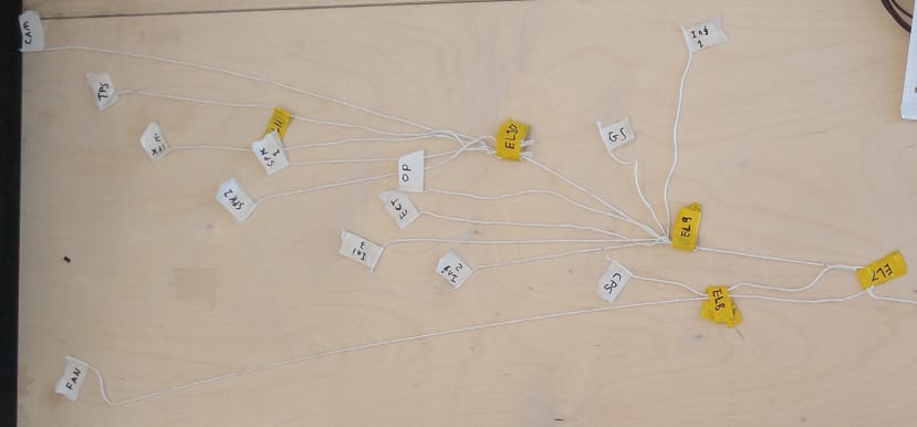
From there, the next step of designing a wiring loom is to measure wire lengths and decide on branching points. This can be done by taping pieces of string to the chassis, where the wires will ultimately go. From this, the “string loom” can be taken out of the car and measured.
This leads to the creation of a loom schematic. The schematic is a useful reference during the manufacturing phase as it provides all the wire lengths. Since this was our first time creating a wiring loom from scratch, we decided to keep each branch separate. This would make it easier to fix any problems, as we could isolate it to a single branch.

Manufacturing
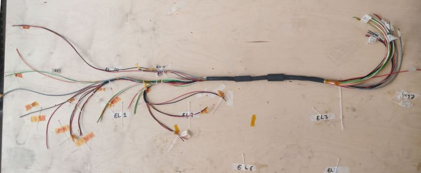
When the manufacturing of the loom is ready to begin, the wires can be cut to length and cable tied to form the structure of the loom. Shielded cables are used for any sensors which might be affected by magnetic interference. Then heat shrink can be applied along each branch. The heat shrink helps keep the wires organised and provides additional protection from damage.
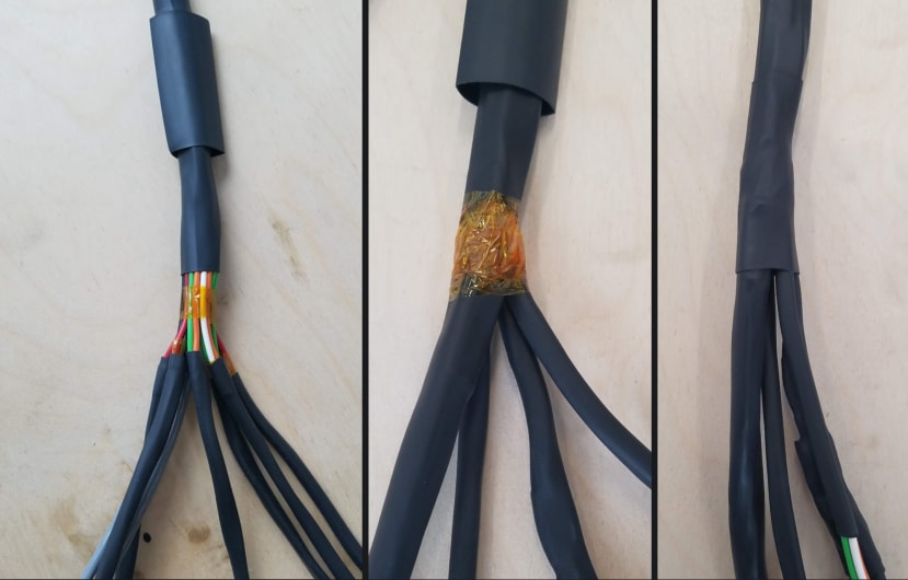
For the branch points, Kapton tape is used to provide stress relief. It also has the benefit of being heat-resistant A heat shrink “boot” is then placed over the branching point.
This process is repeated for each branch until each branch is complete. The picture below is of the engine loom, which includes: fuel injectors, spark plugs, cam sensor, crank sensor, throttle position sensor etc...

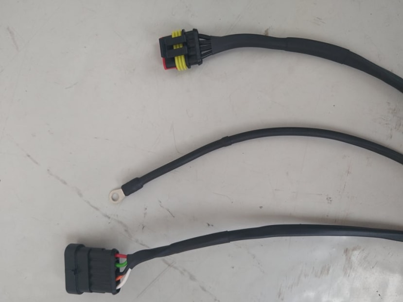
The final step of the manufacturing stage is to add the connectors to the ends of the loom. We use TE connectivity connectors as they are the most cost-effective, and simple to use.
Testing
The very final step is to do a continuity test between each side of the loom to ensure connectors are wired correctly, and that there are no breaks along the wires. The loom can now be placed in the car and tested on the engine. We followed a very modular design, where we used lots of connectors in order to make it easier to isolate problems.