How Full Wave Rectification Works?
Follow article Dave from DesignSpark
How do you feel about this article? Help us to provide better content for you.
Dave from DesignSpark
Thank you! Your feedback has been received.
Dave from DesignSpark
There was a problem submitting your feedback, please try again later.
Dave from DesignSpark
What do you think of this article?
Rectifications are electrical circuits that change AC to DC. Compared to a half-wave rectification circuit, which only rectifies one wave of the input signal, a full-wave rectification corrects both waveforms. It maximizes the usage of the signal while minimizing waste. Therefore, efficiency is at its peak.
Full-wave and half-wave rectification are the two categories to which rectifications belong. Half-wave rectifications lose a lot of power, making them unsuitable for tasks that require a constant and smooth supply. I utilize full wave rectification in proteus to create a smoother and more consistent supply. In this article, I will discuss how full wave rectification works and the basic things you should know about it.
What is a Full Wave Rectification?
Full wave rectifications are a specific type of rectification that transforms the entire AC signal cycle into a pulsing DC signal, one half at a time. Full-wave rectification converts alternating current to DC using numerous diodes. Transforming an AC signal into a DC signal is called full wave rectification.
The term "rectification" describes the process whereby circuits are converted from AC to DC. Assuming the input alternate waveform is rectified in both directions, the rectification is said to be full-wave.
It is accomplished with full-wave rectifications, which use many diodes to correct the voltage. Only one current path can flow through a diode; the opposite direction is blocked.
How Full Wave Rectification Works
As we indicated at the outset, there are two different varieties of this rectification: full-wave bridge rectifications and centre tap full-wave rectifications. Every one of these functions and features is unique. I will explain the characteristics of the two rectifications and how they work.
Center Tap Full-wave Rectification Circuit
In a centre-tapped full-wave rectification circuit, the secondary coil of a transformer, denoted by the notation AB, is tapped in the middle, at location C, and two diodes, D1 and D2, are connected in series across the lower and upper halves of the circuit, respectively.
Diode D1 utilizes the AC voltage across the secondary coil's top half for signal wave rectification. In contrast, Diode D2 utilizes the AC voltage across the bottom half of the secondary coil. Vacuum tubes and thermionic valves both frequently use this rectification.
Center Tapped Rectification Working Operation
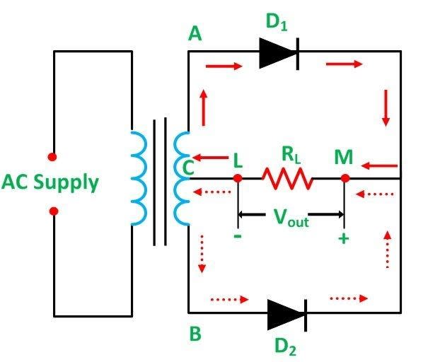
The diagram above depicts the waveform and circuit diagram for a centre-tap full-wave rectification. When you look carefully at the circuit and trace the arrows, you'll see that once you turn on the AC supply, the negative voltage Vin occurs across the endpoints AB of the transformer's secondary coil.
Positive Half Cycle Rectification:
Throughout the positive half-cycle of a particular voltage, the transformer's terminal A gets positive, and terminal B gets negative. As a result, D1 is now forward biased, whereas D2 is reverse biased. It results in D2 not conducting current and only the diode D1 conducting current.
As illustrated in the diagram above, current begins to flow via diode D1, and Vout is recorded across RL. It indicates that the transformer's secondary coil only has current flowing through the upper part of it. Bold arrows indicate the current's flow direction.
Negative Half Cycle Rectification:
The centre-tapped rectification's Negative Half Cycle causes the transformer's terminal B to flip to the positive while terminal A flips to the negative. Due to this, the D1 diode is now forward biased, whereas the D2 diode is now reverse biased. As a result, diode D1 is no longer conducting electricity, whereas diode D2 is.
The arrows indicate how the secondary current flows via the diode D2 and the RL. The current via the RL travels similarly for both the negative and positive halves of the AC Vin. Because of this, there's a production of a DC Vout across the RL. The diagram displays the waveforms of the Vin, the load current, and the Vout created across the RL.
Full Wave Bridge Rectification Circuit
An alternative to the conventional two-diode full-wave rectification is the four-diode bridge rectification. Furthermore, you don't have to centre tap. Considering its moniker, we can infer that it employs a bridge circuit just by knowing it's a rectification that spans two bridges.
These 4 separate rectifying diodes are linked together in a closed-loop bridge arrangement. The full-wave bridge rectification's reduced size and lower price are interesting facts about it. It is so that it is not dependent on a specific centre-tapped transformer manufacturer.
Full-Wave Bridge Rectification Working Operation
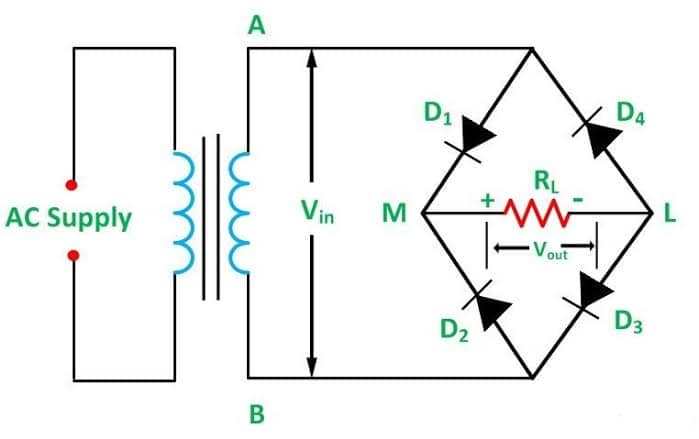
The bridge rectification contains four diodes, designated as D1, D2, D3, and D4, as seen in the above image. Just two of the bridge's four diodes are active at any moment. Assuming you send a negative or positive half cycle to the bridge circuit, "D1 and D3" may conduct, "D2 and D4" may conduct, or vice versa. Let's examine this now while considering both cases:
Positive Half Cycle Rectification:
Due to the presence of positive voltage during the positive half cycle, Diode D2 is positively biased, while Diode D4 is negatively biased. D1 and D3 diodes, however, are negatively biased. "D2 and D4" can conduct according to this.
The figure mentioned above displays the current direction.
Negative Half Cycle Rectification:
Diodes "D1" and "D3" receive a positive bias whenever the negative half cycle is input into the bridge circuit. D2 and D4 diodes, however, exhibit negative bias. Only "D1 and D3" can conduct according to this. The figure above displays the current course.
The most crucial thing to remember is that the stream flows in the same direction in all scenarios. That's because there's only one direction for the current to go in, and thus only one way for the voltage to drop.
Advantages of Full Wave Rectification
- The AC input undergoes rectification during both cycles.
- It's double the input frequency that we see as ripples.
- Efficiency has increased.
- High direct current output.
- Reduced impact of ripples.
- Increased output voltage
- Increased transformer use rate.
- Use of both positive and negative cycles of the AC waveform.
- Since you can easily calculate the ripple frequency, smoothing may be provided more quickly.
Disadvantages of Full Wave Rectification
- More complex than a half-wave rectification
- Centre-tap rectification uses two diodes, while bridge rectification uses four.
- The diode has a better PIV rating than its counterparts.
- More expensive and bulkier diodes with a higher PIV rating are not practical.
- Transformers with centre taps are expensive.
- An audio circuit might be more sensitive to the double-frequency hum.
- Locating the secondary winding centre tap on this rectification is challenging.
- Since just half of the secondary voltage from the transformer was used by each diode, the direct current output is low.
- Full-wave rectification circuits are not practical when only a little voltage needs to be rectified.
Conclusion
Rectifications are electrical circuits that change AC to DC. Half-wave and full-wave rectifications are the two categories into which rectifications fall. With a half-wave rectification, you will get more power loss, and it's not practical for tasks that require a smooth and constant supply.