Familiarising Myself with Filters
Follow article
 Dave from DesignSpark
How do you feel about this article? Help us to provide better content for you.
Dave from DesignSpark
Thank you! Your feedback has been received.
Dave from DesignSpark
There was a problem submitting your feedback, please try again later.
Dave from DesignSpark
What do you think of this article?

Image source: www.electronics-tutorials.ws
Looking at filter basics and their applications.
For anyone who stumbled across this post by accident I’m not going to be talking about water or lens filters — here I’m going to look at something which is almost entirely different — electronic filters. Even though the filters used in coffee machines and the ones used in photography aren’t what I’m going to be looking at today, I think most people would agree that they all operate around the same concept. They filter out the bits you don’t want and let through the bits you do want, regardless of what those ‘bits’ may be.
Filters are used within electronics to emphasize signals within a particular frequency range and reject those which are not in the desired range. To put it simply, electronic filters ‘filter out’ unwanted signals and let through signals within the desired range.
They consist of networks which process signals in a frequency dependant manner and alter the amplitude and/or phase characteristics of a signal with respect to frequency. These can be divided into two distinct types, active and passive. Active filters contain an amplifying device in order to increase the signal, while passive filters only use passive components such as resistors, capacitors etc.
Basic Filters
First let’s took a look at the basic passive filter types. As mentioned above, passive filters only use passive components, therefore do not contain any amplifying elements like transistors or op amps. Low frequency passive filters (100Hz- 100KHz) are usually constructed using RC networks, whereas high frequency passive filters (upwards of 100KHz) are generally constructed from RLC networks.
Regardless of whether the method used to filter out these undesired signals is active or passive, there are four commonly used types of filter design:
Low Pass

Image Source: http://www.electronics-tutorials.ws
A low pass filter only allows signals lower than its cutoff point to pass, signals with frequencies which are above the cutoff point are then blocked. This works by using a combination of capacitance, resistance and sometimes inductance in order to provide high attenuation above its cutoff point and no/very little attenuation below this cutoff point. The high attenuation above the cutoff point blocks the undesired signals.

Image Source: http://www.electronics-tutorials.ws
As the reactance of the capacitor varies inversely with frequency and the resistor value always remains constant, at low frequencies the reactance of the capacitor will be very large in comparison to the resistor value.

Image source: https://dreamitdesignitbuildit.wordpress.com/
A very common application for low pass filters would be on the output of a transmitter. This would prevent any unwanted higher frequency harmonics signals being transmitted and possibly picked up by a higher frequency receiver.
High Pass

Image Source: http://www.electronics-tutorials.ws
A high pass filter is the exact opposite of a low pass filter, in both operation and component layout. Here the capacitor and resistor have swapped places, which results in only high frequency signals being able to pass. Signals with a frequency below the cutoff point of the filter are blocked. This component layout provides high attenuation below the cutoff point and minimal attenuation above it, allowing signals with frequencies greater than the cutoff point to pass.

Image Source: http://www.electronics-tutorials.ws
A common application for high pass filters with the use of audio equipment. A high pass filter may often be put on the input to a microphone pre amp, to prevent any low frequency signals such as mains interference being picked up and combining with the wanted signal.
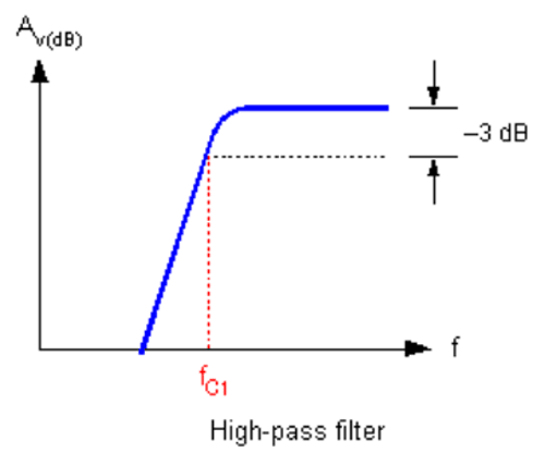
Image source: https://dreamitdesignitbuildit.wordpress.com/
Band Pass
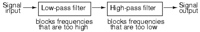
Image source: www.allaboutcircuits.com
A band pass filter is a combination of a low pass and a high pass filter in series in order to create a filter which only allows frequencies within a certain frequency band to pass. Any signals lower than the lower cutoff point and higher than the higher cutoff point are blocked, while frequencies between these two cutoff points are allowed to pass.

Image Source: http://www.electronics-tutorials.ws
One of the applications that band pass filters are used in is a receiver, to limit the bandwidth of the received signal.

Image source: https://dreamitdesignitbuildit.wordpress.com/
Band Stop

Image source: www.allaboutcircuits.com
A band stop is the opposite of a band pass filter. Here this type of filter blocks frequencies within a certain band. Signals with frequencies higher and lower of this band are able to pass but frequencies which lay within this band are then blocked. This also consists of a low pass and high pass filter except here they are placed in parallel in order to achieve blocked signals in a certain band.

Image Source: http://www.electronics-tutorials.ws

Image source: https://dreamitdesignitbuildit.wordpress.com/
Filter performance
The application influences the filter design and in addition to cutoff frequencies, the knee curve also needs to be taken into consideration. I like to think of this as similar to Q-factor — this is the parameter which also describes how under-damped an oscillator or resonator may be — which characterises resonator bandwidth relative to its centre frequency.
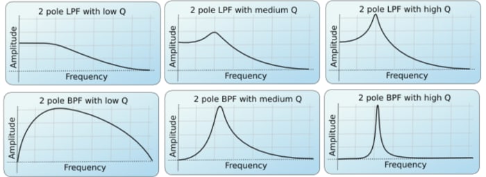
The knee curve needs to be sharp for the best response and a very smooth knee will still let some of the unwanted signals to pass above/below the cutoff point. In many cases, but not all, ideally the knee curve would be as close to the blue line on the diagram below as possible.

Image source: www.wikipedia.org
High Performance & Specialist Filters
Above we looked at some of the most basic filters and now I am going to have a look at some more specialist filters and those with a significantly higher performance.
Crystal filters
Crystal filters are a mechanical type of filer which takes advantage of the piezoelectric properties of quartz and uses this as its resonator. As quartz has a very low coefficient of thermal expansion this means that crystal filters can produce stable frequencies over a wide temperature range.

Image source: www.radio-electronics.com
Crystal filters are used in many applications, including RF. The high Q-factor makes these ideal as the primary band pass RF filter in high performance radio communications receivers. Due to this there are several circuits which have been developed in order to provide the required level of selectivity and performance. These include:
- Single crystal filter – This is the simplest form of crystal filters as this consists of a single crystal. This is a type of RF filter which was used in early receivers (pre 1960) and are very rarely used today. The crystal have a very high Q-factor but the response is asymmetric and is too narrow for the majority of applications.
- Half lattice crystal filter – This is a form of RF band pass filter which provides a significant improvement in performance over the single crystal filter. In this configuration the capacitances of the two crystals cancel each other out, enabling the circuit to operate to a satisfactory level. By adopting a slightly different frequency for the crystals a wider bandwidth can be obtained, having said this the slope response outside of the required pass band quickly falls away and this enables high levels of out of band rejection to be obtained.
- Ladder filter – For many years this was possibly the most popular format of crystal filters to be used. Here all the resonators have the same frequency and there are inter-resonator coupling capacitors between each crystal with the other termination connected to GND. This provides a very high quality intermediate frequency (IF) filter.
Ceramic filters
This type of filter is very similar to a quartz crystal in the manner in which it behaves. It is a compromise between Cavity and Lumped element which takes into consideration both size and performance. While this type of filter is often used in commercial applications it can also be utilised in military and GPS applications. These are widely used throughout RF band pass filter applications for radio transmitters and receivers. These are cheap and easy to use, these are ideal for a range of applications where the performance of the much more costly crystal filters is required.

Image source: www.radio-electronics.com
The ceramics used for manufacturing these filters have piezoelectric properties, this has electrodes plated onto either side in order to produce a resonator. Having a lower Q-factor than quartz results in this type of filter having bandwidths that are typically measured between 0.05 and 20% of the operating frequency. Initially these were manufactured for lower frequency applications, however, with significant investment in the development ceramic filters are now enabled for much higher frequencies and specification levels.
SAW filters
Surface Acoustic Wave (SAW) filters are electromechanical devices which are commonly used in RF applications. Here electrical signals are converted to an acoustic wave by inter-digital transducers on a piezoelectric material such as a crystal or ceramic. The wave is delayed as it propagates across the device and electrodes are used to transmit and receive the waves – here an electrical signal is converted to an acoustic wave and then back into an electrical signal.
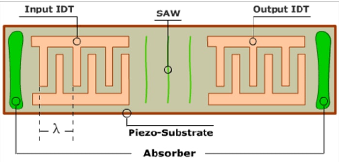
Image source: www.rtxtech.com
Most common SAW filters are band pass filters which are widespread in radio systems and domestic TV. SAW filters come in many different types with varying advantages, some of which include: low shape factor, compact size and high frequency operation. While they have many advantages, they are generally limited to frequencies from 50 MHz up to 3GHz.
Cavity filters
These are a mechanical type of filter which consists of a resonator inside a conducting box with coupling loops ate both the input and output. While tuned circuits which are based around passive components can do the same job as a cavity filter, they can not do it as effectively. A much higher Q-factor and increased performance capabilities can be achieved with cavity filters by increasing the internal volume. Providing cost is not an influence in the design, cavity filters can be better suited to demanding applications due to their higher performance.
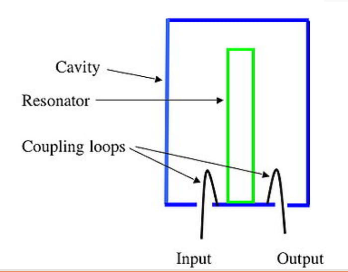
Image source: www.amateur-radio-wiki.net
Cavity filters form one of the fundamental building blocks of a duplexer. A duplexer is an electronic devices which allow bi-directional communication over a single pathway. A duplexer tends to have three ports, one for the transmitter, one for the receiver and one for the antenna. The transmitter and receiver remain isolated from one another while being permitted to share a common antenna. What I find particularly interesting is that they are commonly used in cellular base stations – wireless systems which use SHF radio communication.
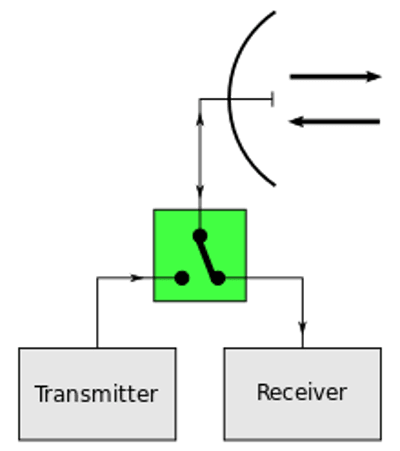
Image source: www.wikipedia.com
Since looking at filters I would like to next attempt to design and build one for myself. I think it would be good to analyse at the output of the one I design and see if the cutoff point is what I have calculated. Be sure to look out for another post where I put filters to use!