Debuging an autonomous robot power supply using a RS Pro programmable power supply unit
Follow article
 Dave from DesignSpark
How do you feel about this article? Help us to provide better content for you.
Dave from DesignSpark
Thank you! Your feedback has been received.
Dave from DesignSpark
There was a problem submitting your feedback, please try again later.
Dave from DesignSpark
What do you think of this article?
At the end of the 2018 French Robotic Cup, our autonomous robot suffered from a loss of around 40% of its maximum motion dynamic. Since it’s a relatively complex piece of mixed technology merging mechanic, « power » electronic, command electronic, low-level software and high-level software: various causes can explain such an issue. In this article, we will show you our debugging process using both custom made software tools and a programmable power supply unit (RSPD 3303X-E), (123-6468) .
It’s highly improbable that it’s a software issue since we can track our changes within git with a gitlab front-end. Since the electronic control signals have been previously checked with a scope, this left us with a most-likely power electronic overload, an electromechanical issue on the engine or a further mechanical problem.
This power supply was given to us by RS and as luck would have it, it allowed us to investigate if the issue was caused by the Robot inner power electronics or by an electromechanical issue on the engines.
In this article we will explore from unboxing to a first test, we will cover ethernet or USB control of the PSU in another article.
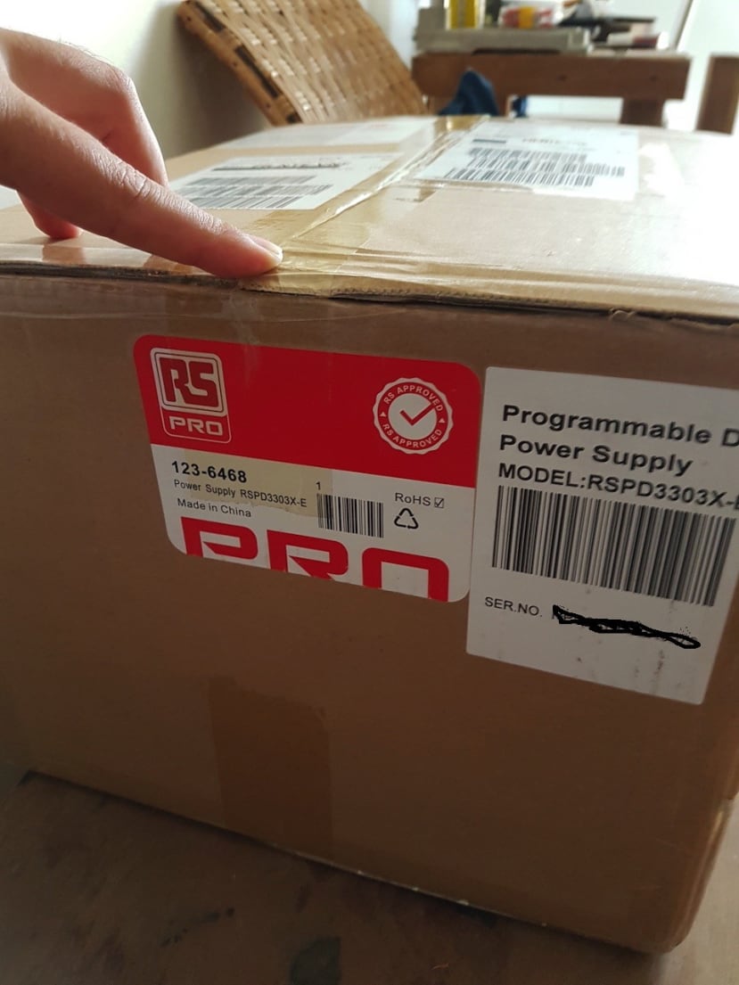
First step: unboxing
The PSU came in a big RS package, nicely packed with the adapted protection for the 8 kg of the unit (linear power supplies are heavy because of the bulky transformer, but provide very smooth voltages).
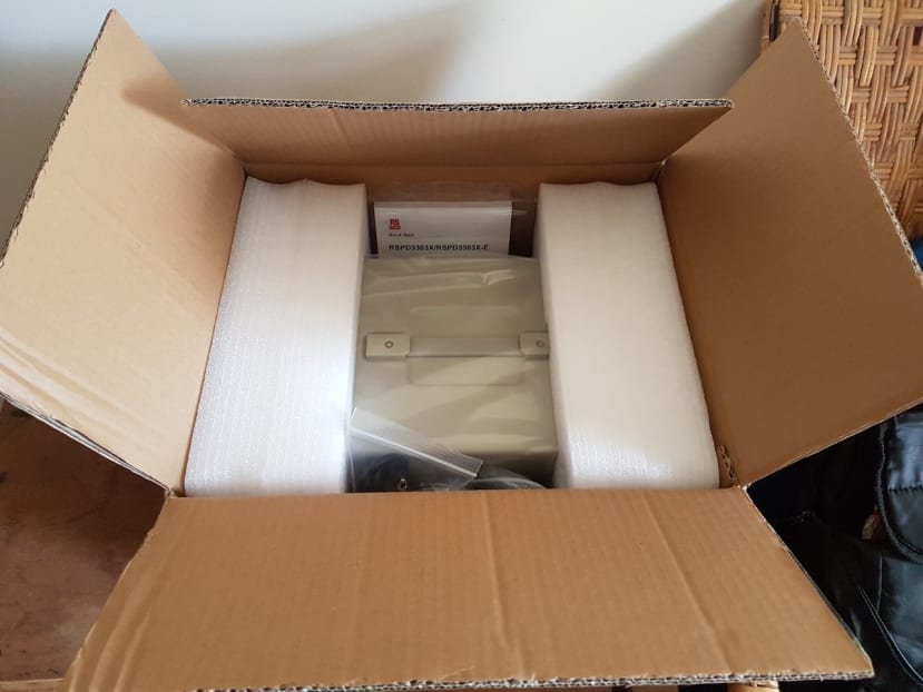
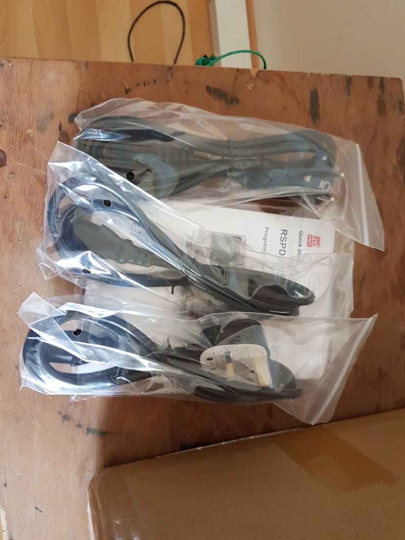
The nicely packed unit comes with all the AC power cords required for common countries including the UK plug and the standard European one (that I'll use in France).
It also includes a nice touch with basic testbench wire set: a set of 4mm banana to crocodile clip (red+black) and a set of crocodile clips to a connector that fits around the screwing mechanism of the banana connector on the power supply (red+black).
Don't forget to configure main voltage setting
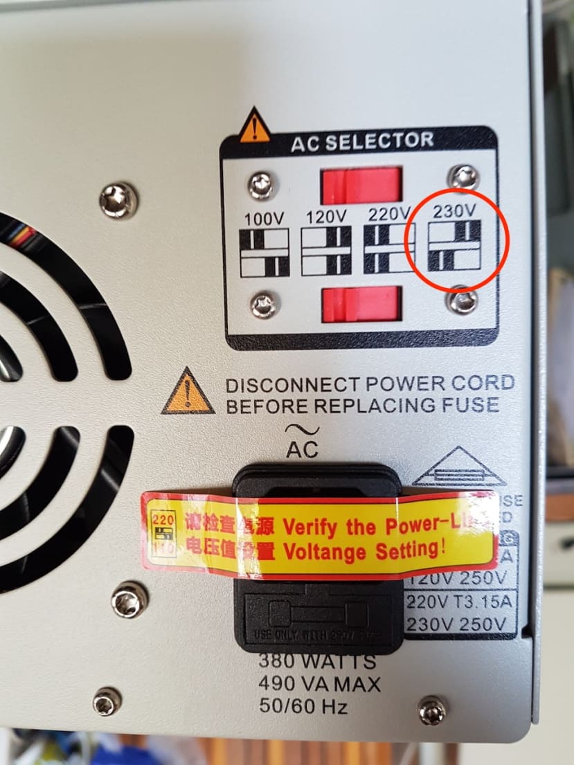
Before powering up the PSU for the first time you have to select the main voltage. It's a rather normal requirement for a linear power supply using a transformer with various tabs. And nice touch again a sticker on the power connector prevents you from forgetting this step!
It's so easy to blow up a nice piece of equipment by forgetting such a setting, this precaution is more than welcomed.
Let's install the PSU on the bench/desk
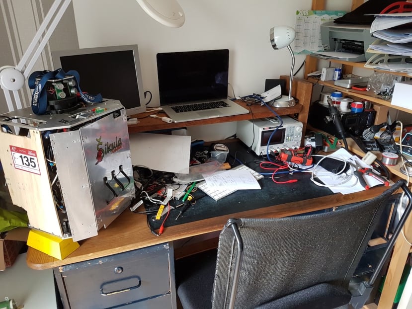
The power supply is just the right size to go under the screen support (custom made here). It will fit nicely on most benches. It's a good thing since when working on a robotics project the bench becomes crowed by many things. Such as a robot, an RS Pro small multimeter, a scope, soldering irons etc
First power-up!
It's quite exciting, a power supply with an LCD screen, you just want to connect it and power it up!
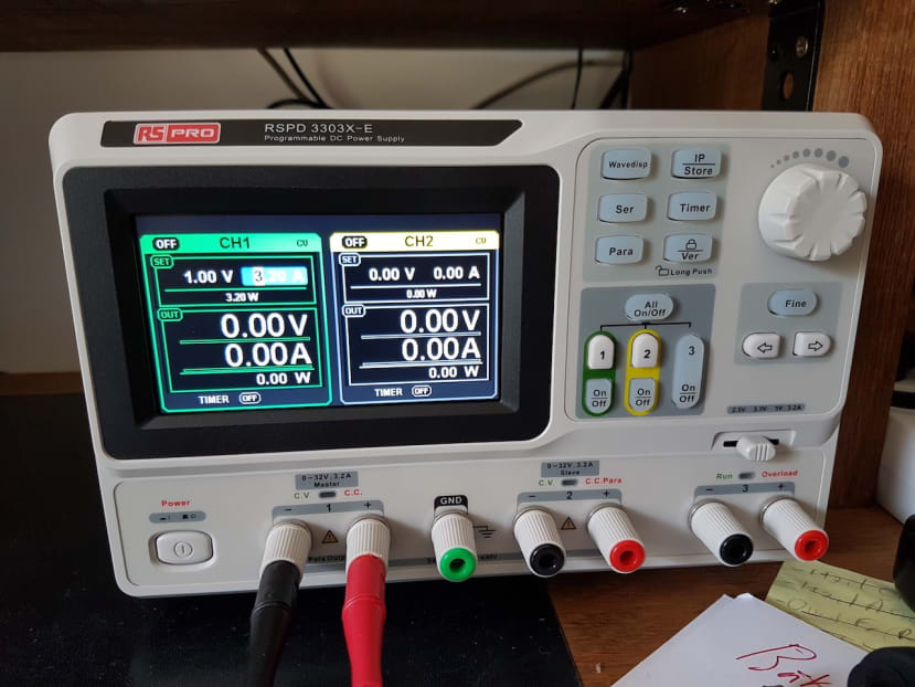
Boot Time under 6s
After a dark screen an "RS Pro" splash screen appears followed by the main control screen, it takes no more than 6s between the hard power switch action and the full availability of the graphical interface.
Noise
The fan is audible but quite silent, however, it's a bit louder when under load, after all, it's a linear power supply, but it's still a lot less noisy than many other bench tools.
HMI First impression
The HMI is quite good, physical buttons feel great, it's rather easy to set voltage and current limit using the rotary encoder, 'fine' button to select which digit and the arrow buttons to jump from one parameter to another. In fact, it's far better than the 1500€ TTI power supply that I use at work, I go at least 2 times faster on this unit.
All the function buttons emit a green light when activated, which is always welcome since it helps a lot to know in which mode the unit is. Each of the 3 output channels has its own dedicated button for this, emitting a nice green light when activated. The output channels also have a nice dedicated signalling LED on top of the output connectors: green is for Constant Voltage and red for Constant Current.
I do however need to mention one point, it's not possible (as far I explored) to put a custom arbitrary limit to the maximum voltage (and current) output.
For example, I was working on a wireless analogue transmission project and I wished to output between 0V and 2.5V. I would have loved to be able to lock the maximum at 2.5V to avoid damage to my wireless module... while being able to change freely between 0 and 2.5V to simulate variation of the measurements. Since this is a software programmed interface I don't see why It couldn't be implemented in the future. Obviously the standard lock everything button is available with a dedicated push button allowing to lock every setting to let a device under test without a post-it for colleagues ("Please do not change, It can put my test on fire").
Channels outputs
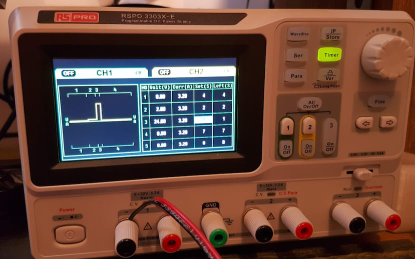
The PSI has three channels: 2 mains 32V 3.2A channels and an auxiliary channel with a selectable voltage (2.5/3.3/5V) with a mechanical switch.
The two main power channels 32V 3.2A are fully configurable with the HMI and with waveforms capabilities, those two channels can be used separately, in parallel (maximum current) and in series (maximum voltage). Relays are integrated to connect the two-channels together by pushing on 'SER' or 'PAR' buttons, the HMI adapts itself, but it's not as easy to perceive as it could be.
The auxiliary 2.5V/3.3V/5V 3.2A channel is a nice touch to connect logic, but as on most power supplies that I've used there is no way to limit it's current output under the maximum of 3.2A and there is no measurement shown on the graphical display.
As far as I've tested with a many digits MTX3293 borrowed from work, the power supply is bang on regarding precision respecting or exceeding specs on all voltages and currents. I was able to test (without burning my test power resistors).
I was quickly able to verify that the outputs are not overshooting on power-up with a scope but it would require a whole new article to really test this in all configurations. This unit seems perfectly ok, so I feel no need to verify this more extensively. However, it's wise to verify this on your lab power supply, to ensure it will not damage circuits under test, other PSU's on the market have such a default, however these are quickly fixed by the manufacturer under warranty.
First power-up!
It's quite exciting a power supply with an LCD screen, you just want to connect it and power it up! But why not test directly something a bit more challenging.
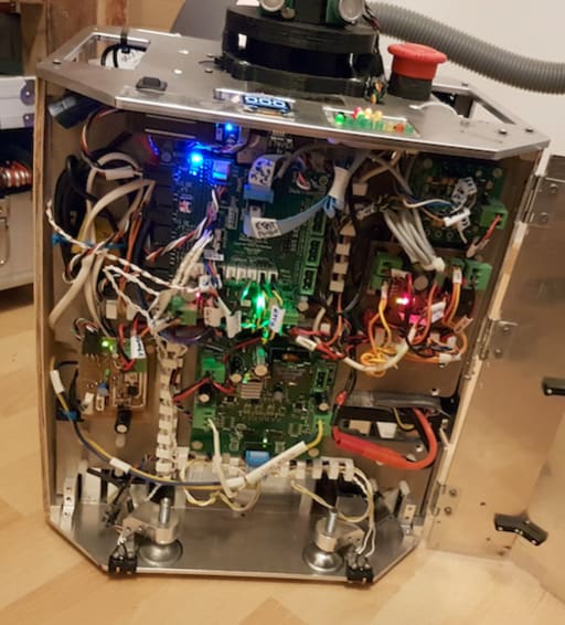
The "Device under test": an autonomous robot for the French Robotic Cup
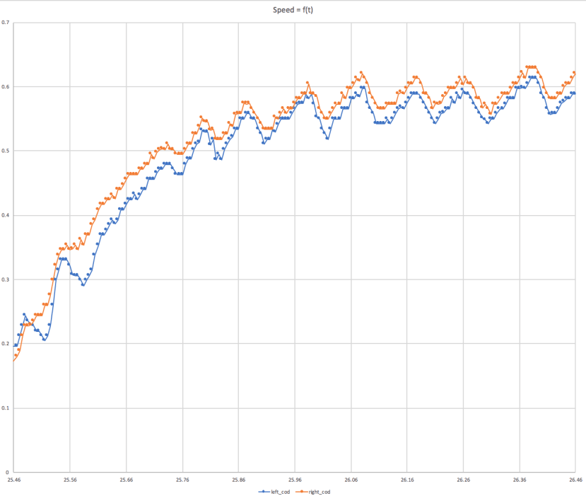
This robot has a relatively complex motion control ensuring high precision of its trajectories. This precision relies partly on engine envelop characterization however, sometimes it loses half of its acceleration capabilities. The idea is to directly power the engine using the programmable power supply in order to generate a 1 or 2s step to get the maximum acceleration using motion data from the onboard sensors and compare it to a 1 or 2s step generated by the embedded power board.
Programmable voltage profile: "2V Ramping + 24V Step"
Using the embedded screen and HMI to programme a step is really easy and practical.
It allowed us to create a ramping part (to mitigate traction issues) followed by a short full speed step.
Real-time measurement of voltage and current
The power supply displays the real-time current and voltage graph which follows the system behaviour under load (here more or less the traction of the robot on the ground).
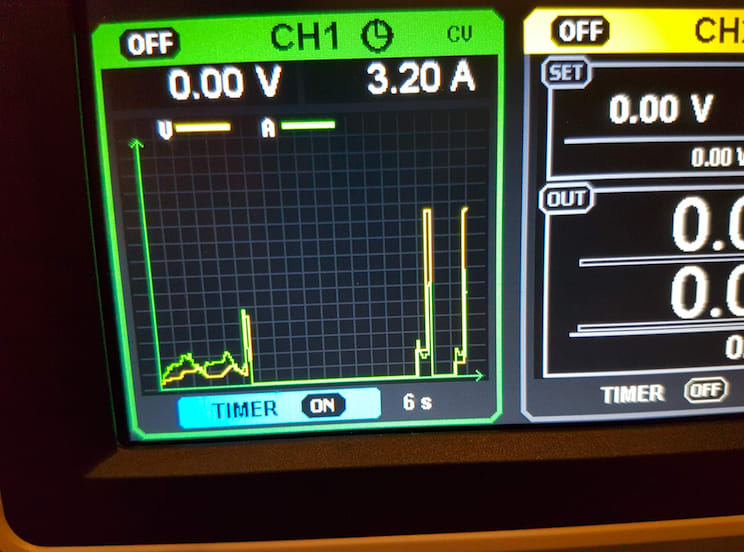
Then we compared both acceleration profiles with the speed from each robot's dedicated speed measuarement wheel with an encoder. The following example shows what profile we can get from a characterization with the embedded power board.
The conclusion was that the maximum acceleration was the same when powered directly by the power supply and using the embedded power board, so we are most likely dealing an engine issue.