Compact Centrifugal fan Packs a Powerful Punch in Advertising
Follow article
 Dave from DesignSpark
How do you feel about this article? Help us to provide better content for you.
Dave from DesignSpark
Thank you! Your feedback has been received.
Dave from DesignSpark
There was a problem submitting your feedback, please try again later.
Dave from DesignSpark
What do you think of this article?
Compact Centrifugal Fan that Packs a Powerful Punch in Advertising
When it comes to state of the art advertising displays, high definition display screens are becoming more commonplace in the high street, where we shop and where we access public transportation systems. The change from static poster displays to screens with content varying throughout the day, creates more interest with eye-catching moving images and bright, colourful, crystal clear graphics. Advertisers can now pick and choose when their products can be shown based on the time of day and the demographic of the people likely to be in the screen location at that time. Being digital the display can include communication functions. This allows the content being advertised to be changed and updated remotely without the need for an operative to carry out maintenance. In this way advertisers can deliver the latest promotional material to a specific audience, making sure that the investment made in publicising their products reaches the highest proportion of their target market.
Integrating this new advertising technology into the high street, outside the supermarket, at bus/tram stops and in our railway stations puts pressure on already crowded real estate. This means that the display units need to be designed to take up the least footprint area, be aesthetically consistent with its surroundings whilst providing the highest quality and functionality. It is essential for advertisers to ensure that the products being promoted are being shown at their best.
The space available to incorporate an electronic display and communication equipment into a weatherproof enclosure requires the equipment to be small resulting in a high-power density. High power densities can lead to high internal ambient temperatures around the display screen which can cause the screen to lose definition. Other influences on the temperature around the display screen include the time of day, the season, local weather conditions and the orientation of the display. On a hot sunny day in June in the UK, the heat load on the display will be at a peak, especially if the sun is shining directly on it. At night time when ambient temperatures drop and solar gain is no longer an issue, the cooling demand will be less.
The displays can be placed in any public location and can be directly exposed to the weather or in relatively sheltered locations. To maintain operational integrity in an outdoor location, sealed enclosures can be used to prevent ingress of humidity, dust and moisture. What stops these contaminants entering also prevents heat generated by the display from escaping. To remove the heat from inside the display enclosure to the external surroundings, the processes of natural convection or conduction do not provide sufficient cooling and some form of forced cooling is necessary. To circulate air over the screen and through the display electronics a compact fan with high volume flow and good pressure development capability is required.
As the operational load is variable depending on the local weather conditions and time of day, variable fan speed control is desirable to reduce the power consumption of the system. Reducing the speed of the fan reduces noise during night-time when there are lower ambient temperatures and less heat load on the display.
Finally, having the display operational all of the time maximises the advertising revenue and product exposure so feedback on the operational status is essential.
In brief, what is required is a small high-performance fan capable of varying its output according to the cooling demand and providing feedback that can be used to check its operating condition
For these reasons, a fan like the RER120 is a perfect match for the task.

Being a backward curved motorised impeller, it is most suited for applications when overcoming the resistance of densely packed electronics and delivering relatively high-volume flows.
Its compact design allows it to fit within the limited space envelope and the DC motor that drives its rotation is capable of running up to a speed of 6,300rpm.
The combination of high speed and characteristic performance of the backward curved motorised impeller provides a high-density power output handing high volumes of air at pressure.
- For 24V DC see (825-7853)
- For 48V DC see (825-7857)


Variable speed also provides benefits on the sound pressure output of the display. For example: reducing the rotational speed by half reduces the sound pressure level output of the fan by -15dB.
A feedback wire provides an open collector tacho output signal. The pulses can be counted to determine the operating speed and the data used to determine if the fan requires a service call.
Interface requirements
Mentioned above, the speed control input is based on a Pulse Width Modulated (PWM) signal. Also mentioned above is that this PWM is a type called Open Collector. Similarly, the speed signal (the Tacho signal), which provides feedback on how fast the fan is running, has been stated as having an open collector output. But what does open collector mean?
Analogue versus Digital
Before the age of electronic control systems, varying the output of induction motor driven devices such as fans, water pumps, escalators to name a few was achieved by increasing the AC voltage to the motor windings gradually until the desired performance was achieved. This method whilst effective, led to weak field conditions in the motor, a loss of efficiency and heat generation in the motor windings.
Other higher efficiency speed control systems were developed that convert AC mains input into high voltage DC and use transistors to send the variable power to the motor windings by changing the frequency and applied voltage at the same time. These frequency converters (commonly known as frequency inverters), provided a more efficient method of varying the output of a motor driven system. Frequency inverters have their own issues that lead to interference and potential damage to the motor if not installed and used correctly.
With the development of computerised control systems there is increasing interaction between controllers and motors using digital communication. This can be either via the form of square wave pulses or by sending commands along a network infrastructure in one of a number of communication protocols. Compact DC fans as well as electronically commutated AC fans can use these digital signals to vary the fan output.
The Use of Transistors to Provide Digital Signals

Transistors are responsible for many of the innovations in the 20th & 21st Century allowing us to miniaturise electronic circuits which are used in computers, mobile communications equipment, transport amongst many other forms of technology.
They are a simple switch that can simply allow or block a flow of current. If the collector and emitter are not connected to a voltage source the transistor can still change state from an insulator to a conductor by energising the base. This will not produce a useable output unless we apply a “Pull-up” resistor to the collector.

Transistors being small electronic devices can only handle relatively low power levels. Should the current flow through the transistor be too great, the transistor will become hot with the risk of burning out. The purpose of the pull-up resistor is to restrict the amount of current flowing in the transistor to levels that will not cause damage or malfunction.
- If the resistance is too low damage may occur as a result of high current flow
- If the resistance is too high the signal at the collector output may be affected by radio wave emissions or may not overcome the pull-down effect of the load
By applying a voltage across the collector and the emitter, and switching the transistor on and off by applying a voltage at the base we can create a square wave output which can be interpreted by a computer or a Programmable Logic Controller as a digital signal (a series of 1’s and 0’s).

Open collector speed control using a Pulse Width Modulation (PWM) signal
We can use a transistor output to provide a digital signal to a DC fan that will determine the speed of rotation. In this case we use what is called a Pulse Width Modulation (PWM) signal. The core principles of a PWM signal are the time period (frequency) with which the signal shall be interpreted and the amount of time that the signal is at a high level during the time period. To make the signal low the transistor is activated to drain the voltage away to ground (or near 0V DC). The ebm-papst St Georgen fan motor shown above can accept a digital signal with a frequency between 2,000 times (2kHz) to 6,000 times (6kHz) per second.

There are also some telecommunications industry fans that are designed to accept a PWM frequency of 25kHz and there are other ebm-papst Mulfingen motors can accept signal frequencies of between 1kHz to 10kHz if used with a pull-up resistor. With any motor that uses a speed control input, its operation manual will explain the type of input and the rage of acceptable frequencies/voltages.
At a PWM frequency of 1kHz, the fan will look at the output of the transistor every millisecond and calculate how long the signal was at a high level for. For a 100% PWM - fan at full speed - the signal will be continuously high. For a 50% PWM - fan at half speed - the signal will be high for half a millisecond (The Mark) and pulled low for the remaining half a millisecond (the space). For 10% PWM - fan at minimum speed - the signal will be high (Mark) for one tenth of a millisecond (100 microseconds) and pulled low (Space) for nine tenths of a millisecond (900 microseconds), etc…
Open Collector Tacho Output for speed Monitoring

Another use of a transistor circuit is to provide a tachometer output that tells us how fast the fan is rotating. There are two types of tacho output provided on ebm-papst products…
- Open collector output allows the user to specify the pull-up voltage and the current flowing through the transistor
- TTL output uses a pull up resistor internal to the fan that provides a voltage signal output (less common)
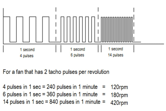
To interpret a tachometer speed signal, we need firstly to know how many voltage pulses there are for each complete revolution of the fan. We can then define a time period over which we will count the pulses – in this case it is 1 second however it could equally be 0.5s, 5s, 10s or other user specified time period. Once we know how many pulses the motor will produce per revolution, the time period that we are counting for and the number of pulses counted in that period we can calculate the fan speed in revolutions per minute (rpm).
The main differences between a tacho output and a PWM input are
- A Tacho signal is a variable frequency fixed mark/space output signal – the frequency changes
- A PWM input is a fixed frequency variable mark/space input signal – the mark space ratio changes
Available Control Devices that provide a PWM output
There are currently three controller types that provide simple control of ebm-papst 4-wire PWM controlled compact fans. The CPC range of controllers offer the following options

CPCXX2040UC-000 - Fan speed based on temperature using an NTC thermistor. Minimum speed at 20oC to maximum speed at 40oC
- For 24V DC see - (667-0380)
- For 48V DC see - (667-0371)
CPCXX3555UC-000 - Fan speed based on temperature using an NTC thermistor. Minimum speed at 35oC to maximum speed at 55oC For 24V DC see…For 48V DC see…
- For 24V DC see - (667-0396)
- For 48V DC see - (667-0387)
CPC48VV10UN-100 - Fan speed based on 0-10V analogue input (Analogue to PWM converter)
- See - (884-1193)
Summary
When it comes to provide cooling in densely packed electronic equipment with limited space constraints, the impeller design and high rotational speed of the RER120 motorised impeller can deliver a high-volume airflow and overcome high internal pressures. On-board speed control facilitates power savings and quieter operation in periods of less thermal load whilst the tacho feedback provides real-time detection of possible operational issues with the fan. Early detection of an operational issue with the fan can be used to call for service assistance before the issue becomes a problem.
With these features built in, the RER120 can interact with the control system ensuring that full operational performance is assured all of the time.