Can I prolong my coin cell battery life with a capacitor?
Follow article
 Dave from DesignSpark
How do you feel about this article? Help us to provide better content for you.
Dave from DesignSpark
Thank you! Your feedback has been received.
Dave from DesignSpark
There was a problem submitting your feedback, please try again later.
Dave from DesignSpark
What do you think of this article?
Most of us working with coin cell batteries have experienced issues with high peak currents, killing the battery. Usually, the question arises: would it be possible to avoid this and prolong my coin cell battery life if I mount a capacitor in parallel with the battery? Browsing through articles on the topic, there seem to be various opinions on whether this works or not. So, I thought that it is time to investigate this once and for all.
The problem
Coin cell batteries are known for their high energy density but also for their sensitivity when it comes to peak currents. We all have seen sensor designs that have had size requirements that were easily solved by choosing a coin cell battery. However, what was most often not taken into consideration were the high peaks in current consumption, for example during the radio transmission. These peaks are famous for emptying the battery. In some cases, you end up with less than 10% of usable battery capacity. If this comes as a surprise late in a development project, it will cause firefighting, huge delays and inevitably high cost.
What to do?
So, you have a design where you’d like to use a coin cell and you know you have high current peaks – what should you do?
First, try to get your current consumption as low as possible – it's the most essential part when working with battery-powered devices. Also, you want to avoid having different parts of the sensor in sync when consuming power. Usually, radio transmissions produce the highest peaks and the stronger the signal the higher the current consumption.
Secondly, do you really need a coin cell battery? An alkaline AAAA battery might handle the peak current much better – if your form factor allows it, of course. High/low temperatures might be an issue here.
Which brings us back to our initial question: “Can I use a capacitor to protect the coin cell from high peak discharge?”
When we introduce a capacitor (or several) in parallel with the battery, we also introduce a leakage current. So, the usable capacity of the battery increases but your device leakage current also increases. Given that adding a capacitor also increases the Bill of Material (BoM) and the physical size of the design, you want to weigh pros and cons before deciding.
Another option might be to go for smaller coin cell batteries but connect two in parallel. My experience is that the thinner the coin cell, the better it can handle peak currents. Speaking to a manufacturer and their experts, it’s perfectly fine to connect two coin cells in parallel without adding a diode. If you have more, diodes are recommended to prevent the best cells damaging the worst.
Capacitors and energy
So, what capacitor type and what capacitance should we choose?
To minimize the leakage current, a Multilayer Ceramic Chip Capacitor (MLCC) seems to be the right choice. However, the capacitance is very limited, and the costs quickly increase. An aluminium electrolytic capacitor might be the better choice to get much larger capacitances for lower costs. But your leakage will increase.
The energy in a capacitor is defined by E=(C*V2)/2 where C is the capacitance and V is the voltage.
In our calculation, the energy that comes from the capacitor is defined by (C*(Vstart−Vstop)2)/2 where Vstart is the battery voltage when the pulse starts and Vstop is the voltage when the pulse ends.
The energy in a pulse is defined by E=P*t where P=U*I and t is the length of the pulse.
Let us define the pulse as 150mA peak for 10ms. This will surely kill a coin cell battery. Calculating the energy, when the voltage is 3V, gives us 4.5mJ in the pulse. When the voltage decreases, the energy in the pulse also decreases but in the calculation example we assume that the current is constant, and the energy varies.
If we let the capacitor voltage drop from 3V to 2V, what capacitance is needed to contain 4.5mJ. The answer is a huge 9000uF. So, it is not realistic to assume that the total energy in the pulse should come from the capacitor.
This raises an interesting question: How big does the capacitor have to be to help the coin cell deliver energy while also increasing the battery life. Let us investigate this!
Setup
For this investigation, I used Otti Arc and Otii Battery Toolbox from Qoitech (obviously :-) (192-3400)
We’ll focus on the CR2450 battery and to be consistent, only use batteries from Energizer. The reason being that they are easy to get and available world-wide.
The capacitors I have chosen are:
- 2x100uF 16V MLCC, C1210C107M4PAC7800 from Kemet
- 470uF 16V aluminium capacitor, UWT1C471MNL1GS from Nichicon
The set-up is as follows, and to improve the statistics I use two setups of each type:
- CR2450 without any capacitor
- CR2450 with 200uF MLCC
- CR2450 with 1x470uF aluminium capacitor
- CR2450 with 2x470uF aluminium capacitor
- CR2450 with 4x470uF aluminium capacitor
- 2 parallel connected CR2032 without diode or capacitor
It comes to a total of 12 battery systems. I let the Otii Arc, using the Otii Battery Toolbox which is a software extension, discharge the batteries from new to empty and investigate how much capacity is available.
When looking at the datasheet of the Energizer CR2450 I see that the stated capacity is 620mAh when discharging with a 7.5kohm resistor. For the CR2032 the same figure is 235mAh when discharging with a 15kohm resistor, so the parallel-connected batteries should, in theory, contain 470mAh. In my setup, I’m expecting a lot less energy.
Execution
In the Otii Battery Toolbox I need to set up the discharge which then looks like this:
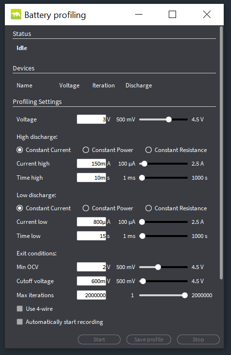
Otii Arc will then discharge the batteries with a 10ms 150mA pulse and then with 800uA for 15s. This will be iterated until either the calculated Open Circuit Voltage (OCV) falls below 2V or the voltage during the high load falls below the cutoff voltage of 600mV.

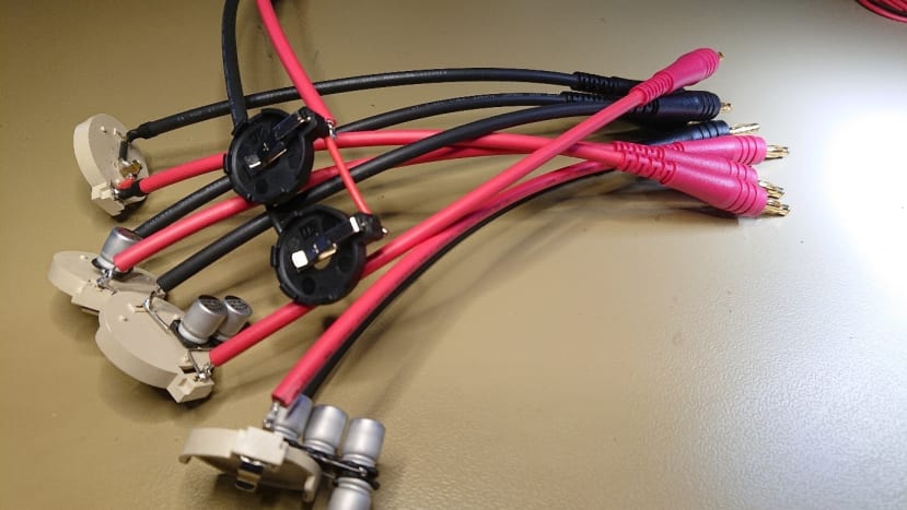
As can be seen in the picture above, I have connected 12 Otii Arcs to one laptop. This is done by using 2 powered USB hubs (TP-Link UH720) to increase the number of USB ports.
Results
So how much energy was I able to discharge before the battery was empty/destroyed? The easiest way to show this is with a graph with the battery system internal resistance for the complete discharge.
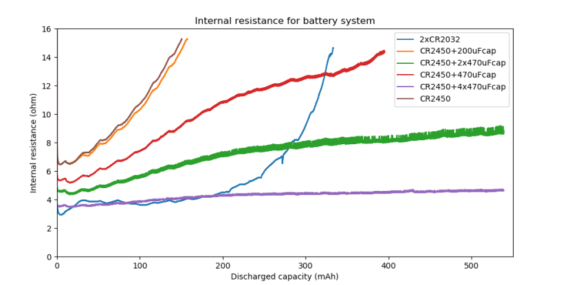
The result for the CR2450 without a capacitor was as expected, poor, and adding 200uF did not help either. The available capacity for these systems is roughly 150mAh. Remember that a capacity of 620mAh was stated, but this is with a different load, so we can only utilize less than 25%.
With two parallel-connected CR2032s, we can use roughly 330mAh while the datasheet states 470mAh - this is 70%, not bad!
With one 470uF capacitor, the available energy is almost 400mAh or 65%. So, the increase in available energy is large even though the capacitor only contains 5% of the pulse energy.
So, what about adding even more capacitance? Here I got a visit from the famous Murphy and when 540mAh was discharged, there was a power out in the building and the profiling stopped. That’s why these systems are only discharged to 540mAh, this is 87% of datasheet capacity.
Looking at the 4x470uF internal resistance curve, at 540mAh the internal resistance is still only 4.7 ohms, so the drop in voltage is not that great during the pulse. During the 150mA pulse, the battery system voltage dropped to 1.8V.

Let us think about the cut-off voltage for your device, meaning when the fun is over, and it stops. In the graph, you can see the battery system voltage during the 150mA pulse plotted. I have also plotted a line for 2.0V. So, at what voltage does your device stops working?
The CR2450, both without capacitance added and with 200uF added, would stop working after 4mAh if the cut-off were 2.0V - this is completely useless. When we added 4x470uF capacitance, the cut-off occurred after 460mAh. Second best is the parallel-connected CR2032 that hit 2.0V after 250mAh.
Does your design have a LED?
Blue and green LEDs typically have a forward voltage above 3V, which is not possible to use when looking at the battery system voltage during the pulse. A red LED is roughly 1.8V, so this is more appropriate.
But let’s plot the graph in a different way. Let’s assume that your device has an average current consumption of 50uA, how long will your battery system last?

In this graph, you can see that the battery lifetime will increase from 3 months to 32 months if you go from one 470uF capacitor to four 470uF capacitors. This is not considering either the added leakage current or the battery self-discharge.
So, what about the added leakage current?
I measured the leakage current for the battery systems when the batteries were removed. The leakage curve is an exponential capacitor charge curve that, when the capacitor is charged, shows the actual leakage.
The CR2450 without capacitor and 2xCR2032 have the same leakage current and that is 0uA since we are measuring an open circuit. They are represented as “open” in the graph below.

I measured leakage current, with Otii, for 4 voltages, 3.5V down to 2.0V with steps of 0.5V. What is interesting is that the highest leakage current does not come from the system with 4 capacitors, but from the system with 2. The leakage current for my 470uF capacitors is obviously different from capacitor to capacitor. So, make sure that you measure an average and take into consideration the effect a really bad capacitor would have. Also, make sure that the temperature during the measurement is the same since the leakage current will be dependent on the temperature.
What is interesting to see is that the 200uF MLCC capacitor leakage current is not that different from one 470uF aluminium capacitor- I measured roughly 70-80nA for them both.
The difference, when changing voltage, is not that great, I have added a graph showing the variations for the system with 4x470uF capacitor as it is the one changing the most.

So, the added leakage current is not that bad compared to how much the available energy has increased.
Conclusion
To answer the original question, can I make my coin cell survive longer by adding capacitors, the answer is YES!
Should you add capacitance and how much should you add?
That is something that needs to be tested for each specific case.
The biggest disadvantage with adding the capacitors, I would say, is the increase in the physical size of your design.