Building the Pollen Pi: A Pollen Indicating Stack Light Display
Follow article
 Dave from DesignSpark
How do you feel about this article? Help us to provide better content for you.
Dave from DesignSpark
Thank you! Your feedback has been received.
Dave from DesignSpark
There was a problem submitting your feedback, please try again later.
Dave from DesignSpark
What do you think of this article?
Combining a USB controlled stack light with a Raspberry Pi and Node-RED to display the local pollen count.
Introduction
In this post, we will be taking a look at web scraping in Node-RED, and then using the retrieved data to control a USB stack light to indicate the local pollen count.
With summer underway here in the UK, pollen counts have skyrocketed, which is particularly problematic for those of us that suffer hay fever. We set out to build a device that’d give a passive indication of the pollen count using a traffic light style stack light.
The Hardware
We started by coming up with ideas on what we wanted to achieve — something that could sit on a desk and give an indication of pollen counts, requiring no user interaction.
A Raspberry Pi (182-6547) was chosen for the processor for this project, as the ability to run Node-RED greatly simplifies the development process (compared to web scraping on a microcontroller, which is typically more resource-constrained). The onboard WiFi present on the Raspberry Pi 3B also means that only a power cable would be necessary for the stack light to work.
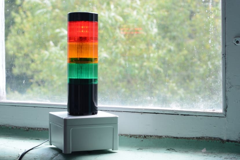
We then moved onto stack light selection. After deciding that a more conventional industrial stack light would require some GPIO interface to provide level shifting — most industrial systems run on 24V whereas the Raspberry Pi GPIO pins are 3.3V, we opted to pick a rather nice Patlite LR6-USB (200-8570) stack light.
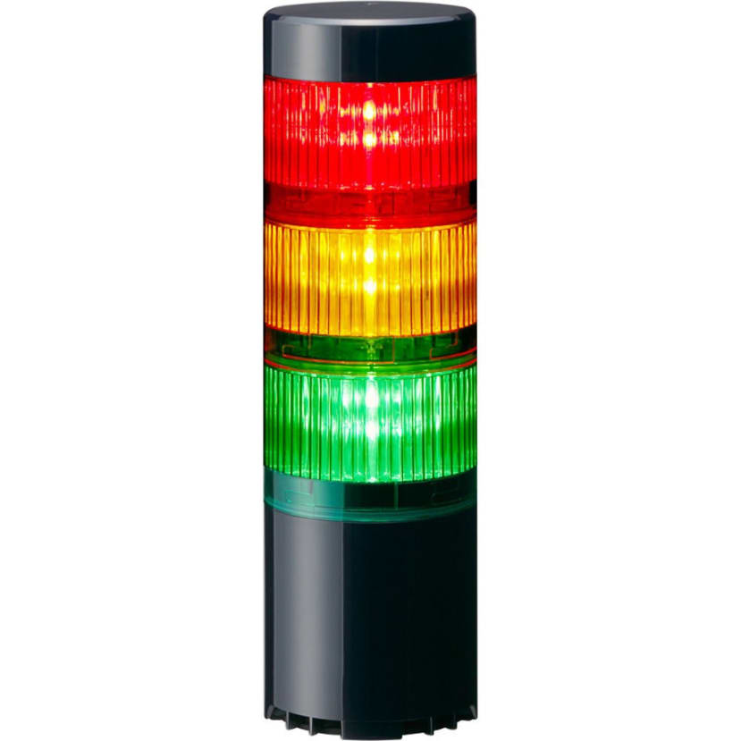
The chosen stack light features a set of red, amber and green LED indicators, an integrated buzzer capable of doing multiple patterns and tones, all of which is powered and controlled over USB.
Patlite provides a DLL for controlling the stack light that will work on x86/x64 systems under Windows and Linux. It is worth noting that we didn’t get this to work under Linux on the ARM processor of the Raspberry Pi (we tried using Python “ctypes” to provide bindings to the DLL) due to the architecture mismatch, but there are alternatives that let us control the light.
A small Fibox enclosure (738-9183) was selected to hold the Pi and mount the stack light. Picking a plastic enclosure was important due to the use of WiFi on the Raspberry Pi — a metal enclosure would act as a faraday cage and block any signal.
The last component is a 5V, 3A plug-top style power supply (903-2879) which has plenty of current to run both the Raspberry Pi and stack light.
To mount the stack light to the lid of the enclosure, a laser-cut template was used as a drilling guide and then three M4 nuts to secure the stack light. A hole was drilled to mount the barrel jack for power input, and then the Raspberry Pi was placed inside the enclosure.
With all the necessary components picked out and assembled, we moved onto the software setup.
The Software
We opted to use Node-RED for this project, as it provides a nice drag-and-drop programming method with a vast library of included blocks to get started with. Having some previous experience with Node-RED also helps, but it is incredibly easy for a beginner to get started with.
Raspberry Pi Setup
To get started, we imaged a suitable micro SD card with the “Raspberry Pi OS Lite” image — this image is suitable for environments that don’t require the full desktop environment, ideal for our “embedded” use case. Win32DiskImager is my preferred tool for writing disk images to storage devices, but the Raspberry Pi Foundation also offers “Raspberry Pi Imager” which also downloads disk images.
We then booted the Pi, ran sudo apt-get update && apt-get upgrade to ensure the system was up-to-date, then sudo raspi-config to configure WiFi and the system hostname. With the Pi configured and the hostname set, we moved on to installing Node-RED.
Node-RED Installation
Installing Node-RED on a Raspberry Pi is as easy as running the install script that is documented in the “Getting Started” guide. This script is also available on GitHub and sets up Node.js and Node-RED with a handful of Raspberry Pi-specific nodes (including ones that can interact with GPIO). The installer also configures a service so that Node-RED will be available once the system has started.
The installer configures Node-RED to run on the default port of 1880, so to ensure that everything was set up properly we accessed our Pi from another PC.
Scraping the Web
With all our tools installed ready to scrape websites, we started looking into how to do this. To get started, we knew that we’d want to update the pollen status at least once per day — the Met Office data changes daily, and includes a five-day forecast. Given this requirement, we started by adding an “inject” node with an interval of 12 hours, so we don’t miss any updates.
With the inject node set up, we could then look into creating an HTTP request — included within Node-RED is a “HTTP request” that supports the common HTTP methods, as well as the ability to set a method by a message passed into the node.

We added the correct URL for the Met Office pollen forecast page to the “URL” field, and left the other values as their default values. Configuring the HTTP request node is as easy as that!

Given we now have the data from a webpage available in “msg.payload”, we worked on extracting the pollen counts from the scraped data. To start with, we identified the element on the web page that contains the pollen count data. This is easy to do using Chrome’s “inspect element” option and then some drilling down to find the element we wanted to target.

A “HTML” parser node was then dropped onto the flow, and the appropriate string was entered for the element selector. This took some trial-and-error to target the right node, but in the end, worked without issue. The settings for the output were left as-is.

To test that we were successfully retrieving pollen count values, a debug node was attached to the output of the HTML parse node. The flow was deployed, and then a manual trigger was injected by clicking the button on the inject node. As can be seen above, we successfully extracted the values that we needed from the webpage.
Controlling the Stack Light
With successful extraction of the pollen values from the Met Office website achieved, we moved onto writing the interface to control the stack light.
As the DLL provided would not work with the ARM architecture, we sent a quick email to the support address for Patlite. A reply was received, including a link to a third-party GitHub repository for controlling the stack light. With this in hand, we tested the stack light using the example file included in that repository.
The first thing of note was that by default the python script required root to run — this is generally regarded as bad practise from a security point of view. However, this was an easy fix, and only required writing a “udev” rule that contained the following line:
SUBSYSTEM=="usb", ATTR{idVendor}=="191a", ATTR{idProduct}=="8003", GROUP="pi", MODE="0666"This allows any user belonging to the “pi” group to read & write to the USB device with the specified VID & PID, in this case, the one for the stack light.
To reload the udev rules without rebooting udevadm control --reload can be run, and the device unplugged then plugged back in to trigger the rule. The example script was then tested again (without the use of sudo).
A simple Python script was written that takes one of “red”, “yellow” or “green” as a command-line argument, and sets the appropriate light colour. The script was then marked as executable using chmod +x stacklight_colour.py

To connect the Node-RED flow with the Python script, a switch node was added with four outputs corresponding to the values of “L”, “M”, “H” and “VH”. Each of these outputs were then tied to an “exec” node that called the script with an appropriate colour as the argument.
With the entire Node-RED flow completed, we tested the system. Clicking the button on the inject node rewarded us with the red light on the stack light being illuminated, corresponding to either high or very high pollen counts — in this case, it was high.
The last step was to run sudo raspi-config once again, and enable the overlay filesystem. This makes the filesystem read-only, but creates an overlay on top that is read-write so that applications can still function as normal — any changes written to an overlay filesystem will not be committed to the storage medium, in this case, the Raspberry Pi SD card.
Should changes need to be made, the overlay filesystem can be disabled from within "raspi-config".
Summing Up
In this article, we have taken a look at how to set up Node-RED, various nodes within to perform web scraping, how to filter for specific elements, and then controlling a real-world device from a Node-RED flow.