Breathe Better Bear- An Air Quality Project. Part 2
Follow article
 Dave from DesignSpark
How do you feel about this article? Help us to provide better content for you.
Dave from DesignSpark
Thank you! Your feedback has been received.
Dave from DesignSpark
There was a problem submitting your feedback, please try again later.
Dave from DesignSpark
What do you think of this article?
Breathe Better Bear Build Guide
For this guide, I'll be providing the laser cutting files as well as the instructions on how to put together the project. The laser-cut files are designed to be used with wood sheets that are 28x48 cm, 3mm thick (12” x 20”, ⅛” thick). In my case, I used Baltic Birch Plywood, but it can be something else.
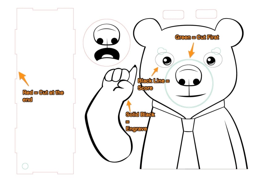
In the SVG files, I have steps separated by colour so they can be easily imported to your laser cutter. Green means cut first since these are holes inside other pieces, red means cut and is used for the bigger pieces, solid black is for engraving, and black lines (no fill) are for scoring.
Also attached to the guide is the 3D print file so you can 3D print the custom piece for the face. The file piece is measured to be compatible with a Micro Servo like this one with the included servo horns.
Step 1 - Sides and Back panels
Relevant Files (see attachments): bear_BottomTopTabs.svg, bear_backpanel.svg, bear_sides.svg
Once the parts have been laser-cut, in this step we will be glueing the sides, top, and bottom panels together.
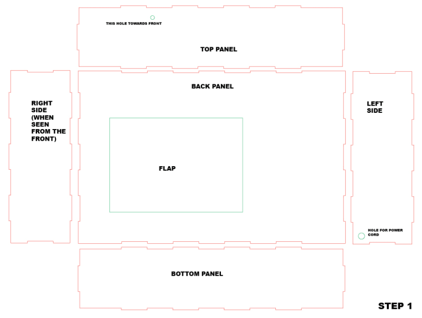
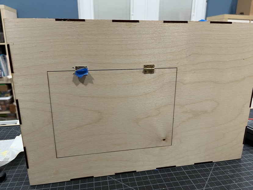
Please be advised that the back panel has an opening that will need hinges. The holes for the hinges are not in the laser-cut files as the hinges I ended up using are not a standard size, but it is easy enough to add the hinges without having the laser-cut holes. It is easier to make the holes before glueing the parts together (do as I say, not as I do as you can see in the photo how I glued before making the holes).
To hold the pieces tight together to dry once I glued them, I added painter's tape.
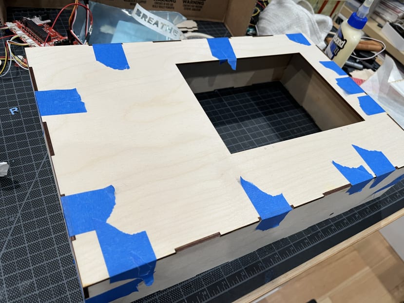
Once the glue dries well, you can attach the flap with the hinges. I used an extra piece of wood inside to function as a stop for the flap to keep it from swinging inside of the box, you can also add a handle to make it easier to pull the flap open (not pictured in the photo).
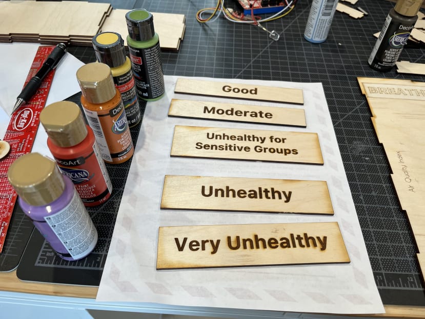
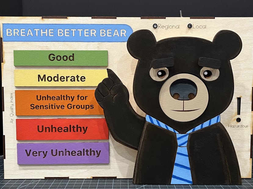
Step 2 - Painting Bear and Air Quality Labels.
Relevant File (see attachments): bear_BearLabels.svg
Laser cutting the bear and the labels will be the most time-consuming part of the laser cutting process as it requires engraving. Instead of engraving, you have the option of scoring and then using paint to fill out the letters and the lines for the bear if you prefer.
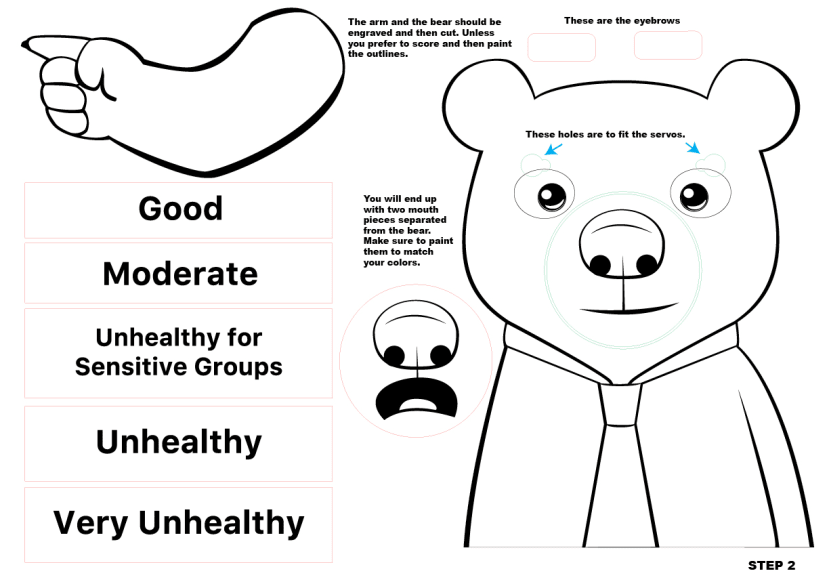
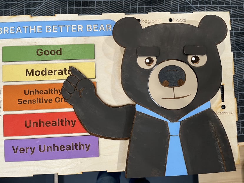
I made my bear a black bear using dark chocolate brown paint.
I tested different effects with the paint on the bear, like this one where it's fuzzier on the edges, but in the end, I went for a more solid fill with lighter edges. (this photo was a test, nothing had been glued at this point)
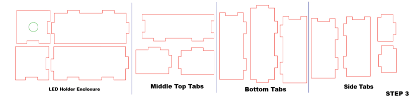
Step 3 - Front panel
Relevant Files (see attachments): bear_frontpanel.svg, bear_BottomTopTabs.svg
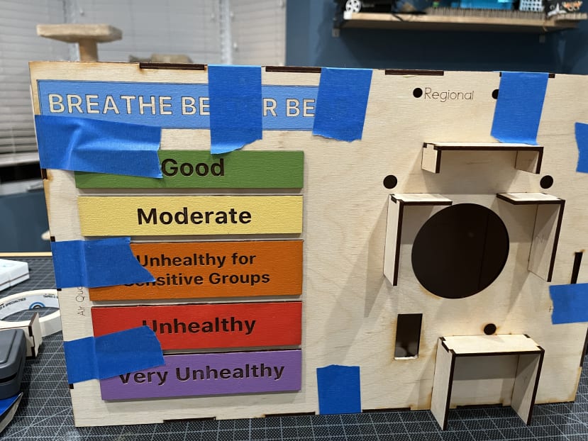
The first step to set up the front panel is to paint the "Breathe Better Bear" label. Once that is dry, you can glue the dry AQI labels next.
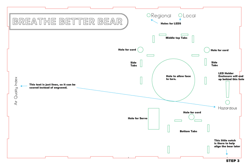
Once the glued labels are dry and fixed, you may glue the tabs that will hold the bear in place and serve as spacers between the bear and the box for the electronics to work. Try fitting the pieces in first before applying glue. For better or worse, the pieces as I designed them only go in one way, so if it's not quite fitting correctly try either a different piece or turn it around. There is some wiggle room, but not too much. Once you figure out the correct placement, apply glue.
While the tabs dry completely, you can now fit the front panel on the box you had previously built with the back and side panels. Glue in place and let dry. (please note I let it dry horizontally and the photo is just to show what it looked like when dry before I took the tape off)
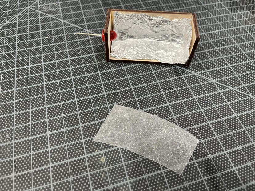
While the box dries, you can put together the LED Holder Enclosure. This piece will be used inside the box behind the exclamation mark. I glued some aluminium foil inside to maximize the reflection of the LED and I found a nice sparkly piece of translucent acrylic to be glued right behind the exclamation mark to cover the hole. This just needs to be big enough to cover the exclamation mark with a little extra to be able to be glued. I chose a red 10mm LED and it is form-fitted to the hole of the pieces.
Step 4 - Bear mouth
Relevant Files (see attachments): bear_BearLabels.svg, Bear Face Parts.stl
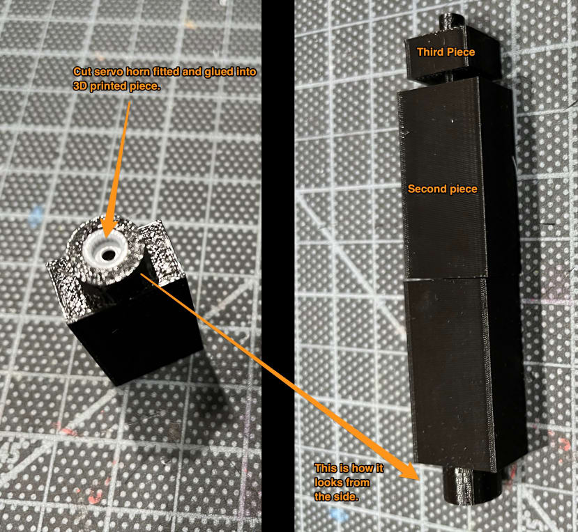
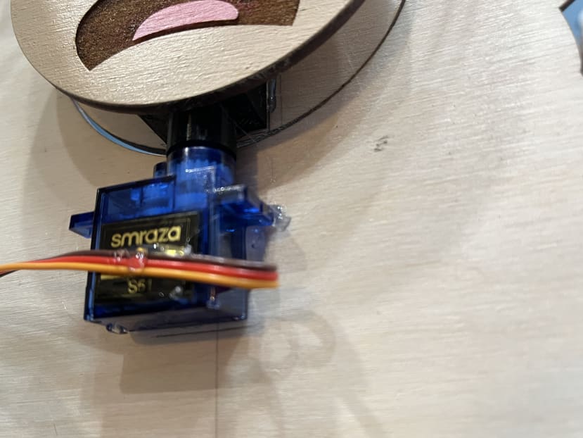
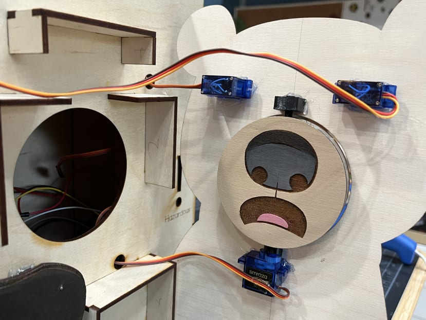
For this step, you will need to 3D print the custom piece I made. You also need to cut one of the servo horns so that only the middle part is left (no arms). This tiny part will need to be glued inside the 3D printed piece that has a hole sized exactly for it and might even need some hammering to get into place. This is done because I could not 3D print the parts with the tiny gears integrated.
Together, the first piece with the cut servo horn and the second piece with the rod at the end span the length of the bear mouth pieces. The idea is that you will glue them onto the back of one of the pieces with the thinnest parts sticking out the circles. Make sure to align it to the middle of the face with the bottom of the face towards the piece with the servo horn.
Once you have the first piece correctly aligned and glued, you need to glue the second mouth piece on the other side, making sure it is also aligned to the middle facing in the same direction as the first one.
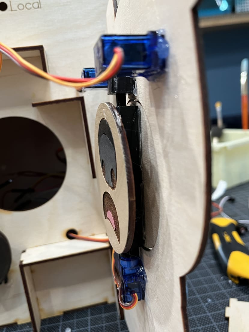
The next photos show the pieces attached to the bear, this will be done in the next step. The photos are just here to show how it'll look so you get a better idea of how to glue the pieces.
Step 5 - Putting it together
At this point, you should have the glued box, the tabs and the labels glued to the front, the painted bear, the arm, the LED enclosure, and the mouths glued to the custom piece.
The next step is to glue the LED enclosure inside the box behind the exclamation mark after glueing the translucent acrylic right behind the exclamation mark hole.
After that is glued and set, you can start with the servos. There are four servos in total, three micro servos, and one standard size servo. The standard size servo moves the arm, two micro servos will move the eyebrows, and the last micro servo turns the mouth around.
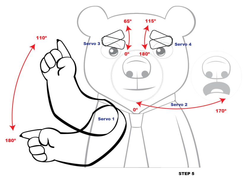
Before glueing or placing the servos, it is recommended to have them be at specific angles to make the mounting of the parts and later coding be easier. For example, the arm of the bear will be connected to servo 1 and by having it be at 180º you can plan on exactly where to place the arm to have that be the lowest point. For the eyebrow servos, the left one (as you are looking at the bear from the front) should be set at 0º and the right at 180º and that will make planning the frown easier once you add the servo horn and glue the eyebrows.
However, the most important servo to set before glueing is the one for the mouth. Because once you glue it, it'll be harder to disconnect the servo from the special piece. Whether you start it at 0º or 180º it has to be one of the extremes, so when you program to do a 180º turn, the mouth will turn to show the other expression.
Please note that while it is preferable to code the servos into position, you can also manually turn them into the correct position using a servo horn.
Here's a diagram of what after trial and error I had the angles of the pieces be. Please note that it might be different for you as each motor can be different. At this point, the only thing you need to worry about is the starting points of the motors.
After you have the motors at the starting degrees, it is time to start mounting them. The first one should be the standard servo that will move the arm. The motor should be pushed through the mounting hole (be careful with the cord, it is a tight fit) with the servo gears towards the top. As soon as it is through, you can put dabs of hot glue to keep it in place. Then you attach the servo horn you'll be using to the servo so you can calculate where the arm will be connected. I used a horn that had big arms so I could add screws at the ends to add more grip since I was worried about the arm being too heavy for the hobby servo to be going up and down without stripping the gears.
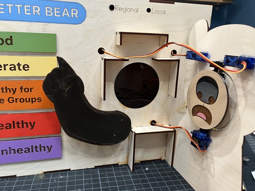
Before you glue the servo horn to the arm or add screws, you need to decide on the placement of the arm. It needs to be able to rotate without hitting the bottom tabs. You can see in the photo where I ended up placing mine, but it was closer to the tabs than it should've been. When you know the arm will rotate comfortably, you should glue the servo horn onto the arm and add screws in the servo horn arms if you want.
Next, you should mount the servos for the eyebrows. They will be sticking out from the back of the bear and only the top will go through the holes. This odd sticking out position will just need to hold until you place the bear where it goes, as the tabs will be supporting the servos afterwards.
Add the servo horns (I chose ones with one arm) to the servos keeping in mind that they should be at the lowest angle to plan for the frown. Then glue the eyebrows with the centre of the gear being at the edge of the eyebrow.
For the mouth, you need to connect the servo to the special piece with the servo horn inside, which at this point should have the pieces sandwiched between the two mouths. Centre the mouth in the hole of the face. You'll need to glue the servo and the 3D printed piece #3. Careful not to add too much glue to the 3D printed piece since it needs to let the rod inside it spin freely.
Once you have all the servos connected to the bear, it is time to mount the bear to the tabs. First, make sure the servo cords all go through the holes made for them. You will need to add glue to the tops of the tabs and then place the bear with the electronics on them. There is a small notch on the front of the box by the lower right corner that will help you align the bear into place.
Step 6 - Connect the electronics.
When the glue sets completely on the bear as it was connected to the box, it is time to add the electronics.
The top of the box has a hole for the toggle switch. There are two holes in the front for LEDs for the Regional and Local settings. Please note that I used plastic LED mounts here, but you can also glue the LEDs in place (If you use hot glue be careful as extreme heat can ruin LEDs).
Here's a diagram of the connections, as I made them when using a REKA:Bit board:
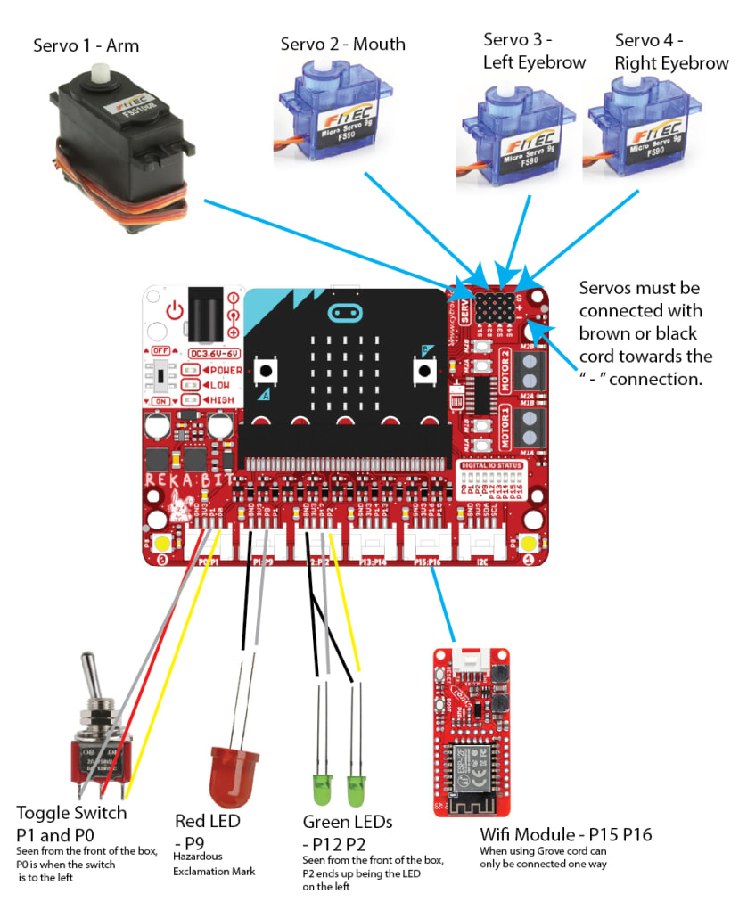
For the connections of the Toggle Switch and the LEDs, I used Grove 4 pin to female cables, so that means extra cords that I just set aside. I kept the soldering to a minimum using jumper cables when necessary, but the green LEDs share a ground so that needed to be spliced.
All the electronics fit comfortably inside the box and you can also fit the DesignSpark Sensor Development Kit.
Next Up
In Part 3 I will be talking about coding the project with the IoT connection.