6 steps to choosing and installing an ESD working surface
Follow article
 Dave from DesignSpark
How do you feel about this article? Help us to provide better content for you.
Dave from DesignSpark
Thank you! Your feedback has been received.
Dave from DesignSpark
There was a problem submitting your feedback, please try again later.
Dave from DesignSpark
What do you think of this article?
The purpose of an ESD protective working surface is to aid in the prevention of damage to ESD sensitive items (ESDS) and assemblies from electrostatic discharge. An ESD protective working surface provides protection in the following two ways:
- Providing a low charging (antistatic) working surface area that will limit static electricity to be generated below potentially damaging levels.
- Removing the electrostatic charge from conductive objects placed on the working surface.
1. Types of ESD working surface
ESD protective working surfaces are categorised into two general categories: conductive and dissipative.
A conductive working surface is defined by most documents as a material that has a surface resistance of less than 1 x 10⁴ ohms. Conductive materials are the quickest to ground a charge but they can also cause damage by discharging too rapidly. Conductive materials are usually used as floor mats or flooring products.
A dissipative working surface is defined as being materials having a surface resistance of at least 1 x 10⁴, but less than 1 x 10⁹ ohms. Dissipative materials will dissipate a charge slower and are recommended for handling electronic components. Dissipative materials are usually the preferred choice for bench top working surfaces.
Most people in the industry consider working surfaces to be the second most important part of an ESD Control Programme, with personnel grounding being most important.
2. Grounding Methods for working surfaces
Method 1: Grounding via ground cords
- Vermason recommends using an earth bonding point cord when grounding via ground cords. Most earth bonding point cords will ground an ESD protective working surface and provide banana jacks for two wrist strap grounds.
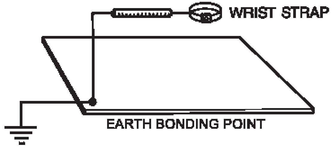
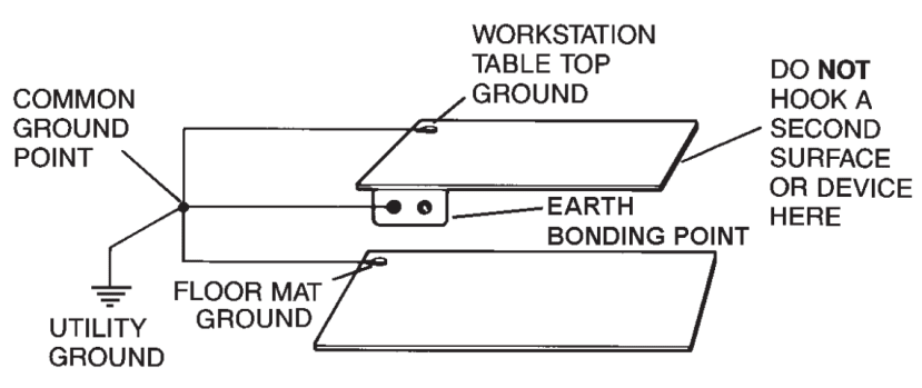
Earth Bonding Point for each workstation
- An earth bonding point should be installed at each workstation and should be connected directly to a verified electrical system ground or to a verified grounding bus which is connected to the protective earth ground. Only one groundable point should be installed on a working surface.
- Wrist straps should never be grounded through a working surface, as the added resistance of the working surface material will prevent the wrist strap from operating properly.
Proper Grounding of Wrist Straps
Method 2: Grounding via a grounded conductive surface
- This alternate form of grounding should only be employed when using a homogeneous dissipative material with a volume resistance of less than 1 x 10⁸
- The dissipative working surface may be placed on a properly grounded laminate, metal or other conductive surface. The working surface will electrically couple to the grounded surface and may not require a separate ground cord.
- When using this type of grounding method be sure to test that the working surface Rg is less than 1 x 10⁹ ohms, tested per IEC 61340-2-3. Also consider increasing Compliance Verification test frequency.
Alternate Grounding Method via a Grounded Conductive Surface
3. Groundable Point Installation
Before installing a groundable point on your work surface you must first determine whether you will need a male stud or female socket, the type of snap hardware and the desired location. There are generally 3 types of groundable points available for working surface mats: screw-on snap kits, push & clinch snaps (with prongs) or stud & posts sets (requiring installation using a punch and an anvil).

Snap Kits and Tools
Screw-on Snaps:
- Determine the position of the grounding snap (one only per mat). Punch a hole through the material with a small Phillips screwdriver or awl.
- Insert the screw through the bottom on the snap fastener, the washer and the material. Affix the assembly with the conical nut supplied with the kit and tighten down the screws.

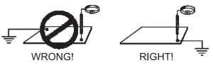
Installing a screw-on Mat Grounding SnapPush & clinch snaps:This snap is designed for use with any type of soft mat material: dissipative, conductive or multi-layered. It is recommended for use with three-layered material, because it provides better contact with the internal conductive layer. It is recommended that before inserting this snap, the mat be punctured with a sharp tool where the snap will be placed. Centre the prongs on the snap assembly. Apply pressure to the snap until the prongs come through the back of the mat, then clinch over prongs making flat to the mat’s bottom side to secure snap as shown in the below picture.
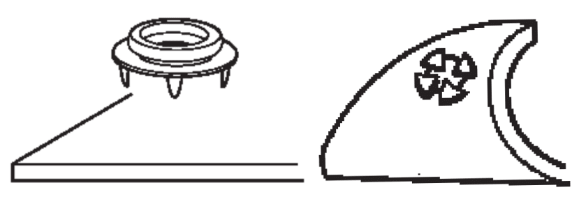
Installing Push & Clinch Mat Grounding SnapStud & post sets:This type of groundable point must be riveted through bench and floor mats to connect ground cords. A punch and anvil are simple but effective tools to achieve a neat finish with firm materials no more than 4mm thick.
- Punch a 5mm diameter hole at the desired location of the mat.
- Insert the post from underneath and apply the stud over the protruding post on the top side.
- Fit the anvil under the post and place the punch inside the stud and hammer the post (or use an arbor press) until it rolls and a tight assembly is achieved.
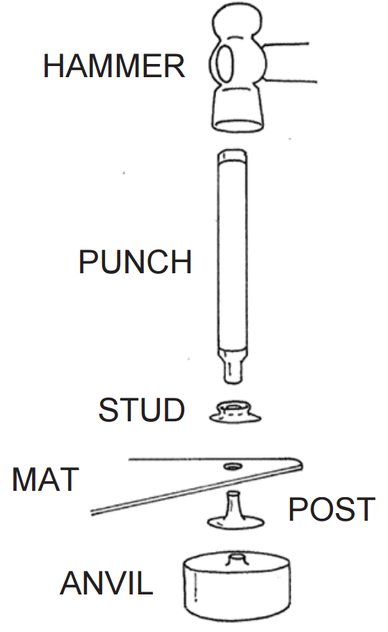
Using a Punch and Anvil to install Stud & Post Sets4. Selection of Common Point & Floor Mat Grounding Systems
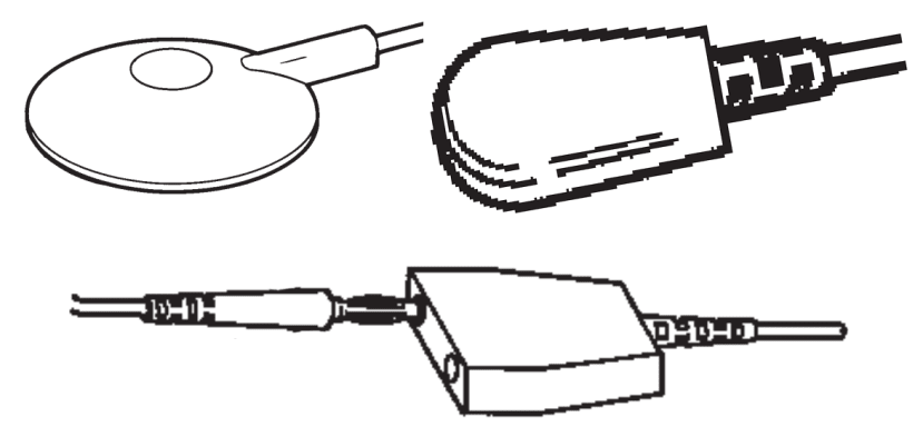
- Determine the type of common point grounding system you will use: barrier strip, bus bar, grounding block or common point ground cord. Vermason recommends the use of common point ground cords and earth bonding bars.
- If you determine that you will use ground cords, you must now determine the type of ground cord you will use for your workstation grounds. It is the user’s preference to use a ground cord with or without a current limiting 1 megohm resistor to ground working surfaces or floor mats. Selection of the ground cord is determined by user needs and specifications; the resistor is not for ESD control.
Examples of Grounding Cords
- Earth bonding point bars allow the grounding of multiple operators at one common ground point. They also mount easily under the front edge of a workstation benchtop.
Earth Bonding Point Installation5. Mat Installation
- For best results, allow the mats to lay flat for about four hours at room temperature before installing. This will give the material time to flatten out from being rolled for shipment.
- Test all workstation grounds for proper resistance to ground.
- Lay the mat in position and snap the ground cord to it. Bring the other end of the ground cord to the common ground point (or earth bonding bar) and attach it using the ring terminal (or other termination device). The electrical systems junction box and connecting conduit should also connect to earth protective ground. Tie the ground wire to the bench to keep it out of the way and neat. You may cut and strip the ground wire to a shorter length and attach it with an extra ring terminal if required.
Note: DO NOT DAISY CHAIN. Because of the high resistances inherent to many types of protective surfaces, daisy chaining of these materials can cause the overall resistance to exceed the required limit of EN 61340-5-1.
ESD working surface should never be grounded in series, i.e. daisy chained
- If your kit includes a floor mat, you should duplicate step 2 and attach the floor mat ground to the same ground point as the working surface ground.
- Measure the resistance from the ground snap on the mat to the common ground point. It should read 1 megohm ±20 percent if you are using a ground cord with a resistor, and less than 10 ohms if you are using a ground cord without a resistor.
- If you have a surface resistance or resistance to ground tester available, you may wish to test the resistance to ground from the mat surface. Note: depending upon the accuracy of the instrument you are using, you may get a wide range of results in resistance to ground tests. In order to get the electrical readings specified per EN 61340-2-3, two 2.2kg electrodes are to be used. This will require a megohmmeter with 100 volt open test circuit voltage and two 2.2kg electrodes.
- If you are using a mat kit that includes the wrist strap, install the wrist strap directly to the common point mat ground cord. Again, test the resistance from the backplate of the wrist strap to the common ground point. It should read 1 megohm ± 20 percent.
Adding a Wrist Strap
- Your completed installation of an ESD workstation should comply with one of the electrical diagrams illustrated below.


Proper wiring diagrams for conductive and dissipative ESD workstations
6. Maintenance and Cleaning For optimum performance, periodic cleaning is required following the manufacturer’s recommendations.BE SURE YOU TEST ALL GROUNDS AND THE WRIST STRAP FREQUENTLY