3D View - Libraries that contain the component models.
Follow article
 Dave from DesignSpark
How do you feel about this article? Help us to provide better content for you.
Dave from DesignSpark
Thank you! Your feedback has been received.
Dave from DesignSpark
There was a problem submitting your feedback, please try again later.
Dave from DesignSpark
What do you think of this article?
The following shows the library structure and which libraries must be enabled for the 3D View to correctly render the PCB. These images were captured from DSPCB Engineer subscription, but DSPCB is very similar using the appropriate folder path names.
From the "Library Manager", select the Folders tab. If the "Default" library is not enabled (greyed out), select to highlight and check the "Folder Enabled" check box.
In the lower window area you will see four supplied folders of type .pkg, these contain the 3D models and must be enabled.

Next, select the "3D View" tab.
To be able to see the available 3D component models select "All Libraries" and the list will be fully populated.

With the "Preview" checked, select any component and you will be able to see the component model and footprint symbol. The PgUp and PgDn keyboard keys can be used to move up and down the list or individual components can be examined by selecting with a left-click of the mouse.

A further useful feature is the "Report" button which can be configured to generate component model reports and their use within the libraries.
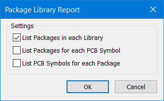
An example using the above is

For further information, the built-in Help files include many details in the Index under 3D.... and Edit 3D Package.
Engineer subscription version has additional 3D options as covered in Help and the Engineer Users Guide.