Arduino design challenge - 120/240 Volt powered Arduino with motion Sensing and Activated Relay
Follow article
 Dave from DesignSpark
How do you feel about this article? Help us to provide better content for you.
Dave from DesignSpark
Thank you! Your feedback has been received.
Dave from DesignSpark
There was a problem submitting your feedback, please try again later.
Dave from DesignSpark
What do you think of this article?
This project incorporates an Arduino, Helium Gateway and Radio, a 120/240 Volt Power Shield with Relay of my own design, Motion Sensors and a Sensor Shield of my own design as well.
I have provided the Gerber files, design Files in Fritzing format, the 3D files for making your own Orb, programming code and a Bill of Materials for everything.
**Important Note**
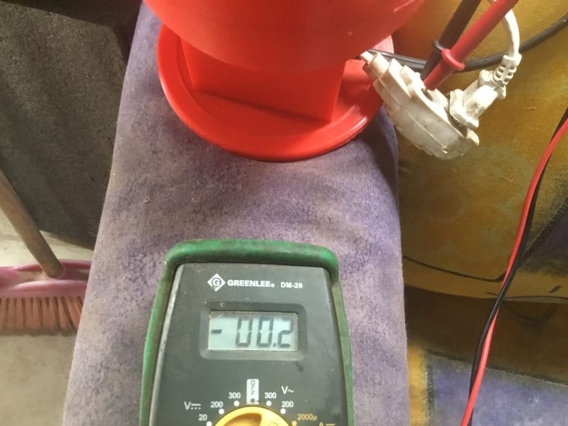
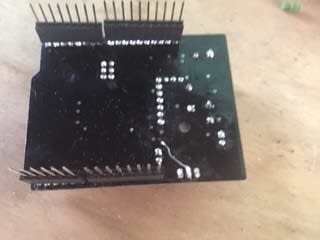
Before starting this project you should be aware that you are hooking 120/240 volts AC to your Arduino. These voltages could be deadly and or cause a fire if you overload the relay or solder it wrong. You can also be seriously hurt if you don’t use proper work and safety ethic. Do not work on the Arduino while it is plugged into power. You should only have the power plug plugged in if it is inside the 3D Printed Orb and ready to be tested and/or completed. TEST THE SHIELD BEFORE YOU PLUG IT INTO the Arduino using a voltmeter to ensure that 5 volts DC is the output on the VIN pin of the shield. Be very careful not to come into contact with the high voltage side of the shield. As you can see from the included images, I used silicone to isolate the power pins on the underside of the shield. Hot glue would work as well.
This project is split into the following parts:
Part 1: Power Supply Shield with Relay
Part 2: Sensor Shield with quick connects and Sensors
Part 3: Helium Shield and Accessories
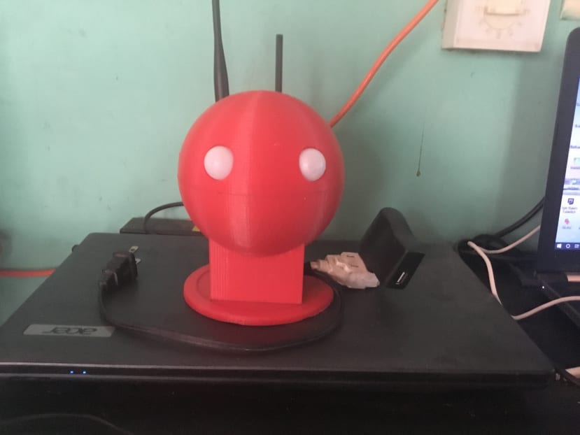
Part 4: 3D Printed Orb with Motion Sensors
Part 5: Programming
Part 6: Putting it all together
Part 7: Final Product
This project showcases my power shield in addition to my sensor shield. The sensor shield has an RN2903 I2C power sensor capable of measuring up to 80VDC and 10 Amps, which can be used for monitoring solar power setups and power usage utilizing a current transformer. It also has a DS181 temperature sensor non-I2C for a base temperature reading. I also added an altimeter pressure chip (output is I2C providing altitude, temperature, pressure). There is also a humidity temperature chip on the board providing temperature and humidity via I2C, and last but not least, there is an air quality sensor measuring VOC and CO2 readings.
https://www.mouser.mx/datasheet/2/682/Sensirion_Humidity_Sensors_SHTC3_Datasheet-1386761.pdf
PART 1: Power Supply Shield with Relay
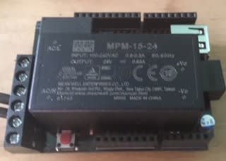
I designed the shield to fit on the Arduino R3 or the Arduino Mega. I used a commercially available through-hole design and certified power supply module for this project.
I used a program called Fritzing ( http://www.fritzing.com) as they have a pretty good Adruino Shield blank to work with and the program is easy to use for beginner PCB design.
I ordered the PCBs from (http://www.PCBway.com) from China. The basic cost for the board is $5.00 plus shipping for 5 boards. Which leaves some room for mistakes. The board is easy to solder as there aren't many solderable pieces.

Image shows PCB without parts and pieces before soldering:

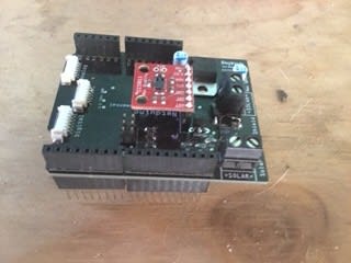
Image shows the bottom of the PCB soldered and with silicone on the 120/240 Volt parts to prevent shocks and shorts.

Part 2: Sensor Shield with quick connects and Sensors

Part 3: Helium Shield and Accessories
https://www.sparkfun.com/products/14547
The Helium Ethernet Starter Kit for Arduino provides everything required to give your embedded devices long-range and secure connectivity. The kit was built specifically for Arduino to get it ready for wireless and IoT applications.
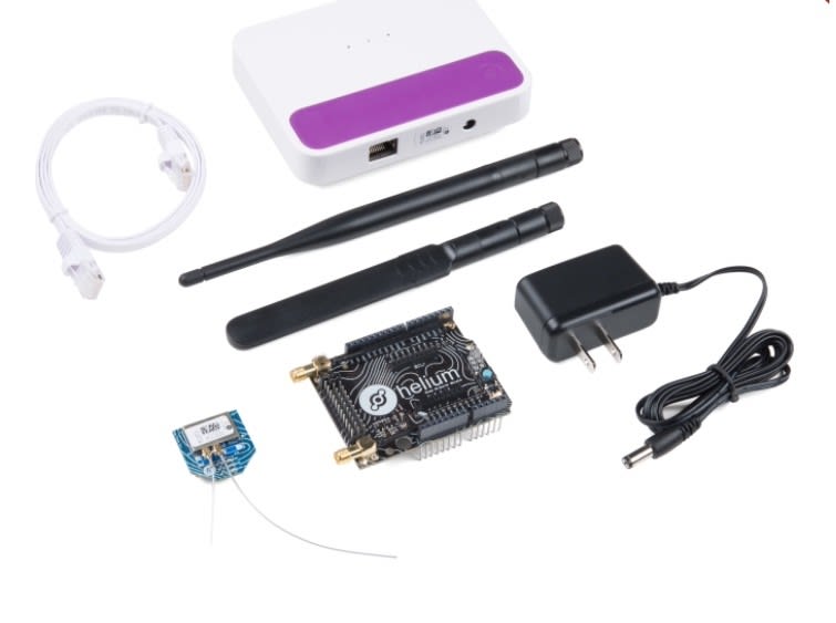
Included in this version is:
- Helium Arduino/mbed Adapter
- Shield with two SMA connectors and an Atom socket in an R3 layout
- One 2.4GHz and one Sub-GHz antenna
- Helium Atom Prototyping Module
- Helium Element Access Point for Ethernet connectivity
- Ethernet cable
- Power adapter
The only thing you need to supply yourself is an Arduino development board (like Arduino Uno R3) and a way to power it!

Since Helium is a complete toolkit for building IoT applications that can connect to public clouds, a pre-built, secure connection from Atom modules interacts with what are called Helium Channels. Channels are a convenience layer between sensors and your organization’s cloud of choice that can connect to public clouds like Amazon Web Services, Azure, Google Cloud IoT Core or a private offering. Channels can also be used to send device data to applications and services via generic protocols like HTTP and MQTT.
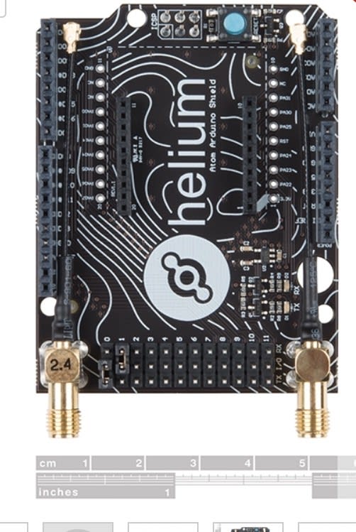
The Helium Atom Prototyping Module is a low-power, dual-band wireless module perfect for developers. The pin layout is compatible with many existing embedded devices. Atom devices connect to the nearest Element Access Point using Helium’s wireless technology, which allows those boards to communicate long distances with little interference and requiring no device-level configuration. Don’t worry; each Element Access Point can support multiple Atoms.
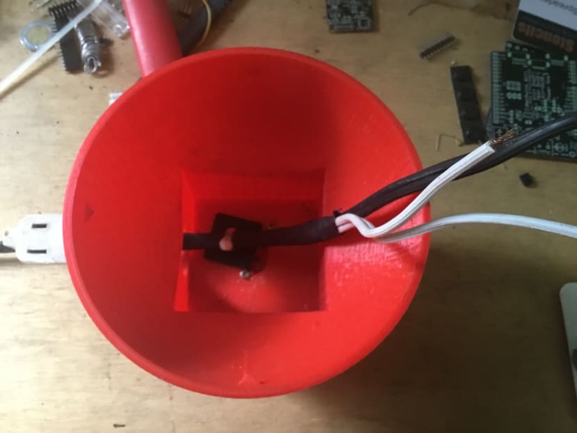
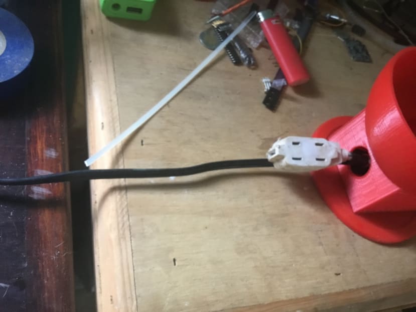
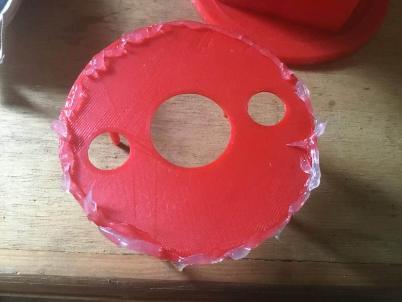
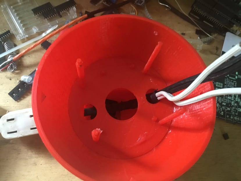
Part 4: 3D Printed Orb with Motion Sensors


Part 5: Programming
https://github.com/adafruit/Adafruit_CCS811
The Arduino CODE is below. You can copy and paste it, but you will need to go to github.com to get the required libraries.
#include "Arduino.h"
#include "Board.h"
#include "Helium.h"
#include "HeliumUtil.h"
#include "SparkFunCCS811.h"
#include <OneWire.h>
#include <DS18B20.h>//(Temperature Sensor)
#include<stdio.h>
#define BUFSIZE 9
#if I2CDEV_IMPLEMENTATION == I2CDEV_ARDUINO_WIRE
#include "Wire.h"
#include "MPL3115A2.h"
#endif
#define LTCADDR 0x69//Table 1 both LOW (7bit address)

#define CCS811_ADDR 0x66 //Default I2C Address
//#define CCS811_ADDR 0x5A //Alternate I2C Address

CCS811 mySensor(CCS811_ADDR);

byte ADCvinMSB, ADCvinLSB, curSenseMSB, curSenseLSB, AinVMSB, AinVLSB;
unsigned int ADCvin, ADCcur, AinV;
float inputVoltage, ADCvoltage, current10, current1, current0p1, current0p01;

int reading1;
#define CHANNEL_NAME "Helium MQTT"
Helium helium(&atom_serial);
Channel channel(&helium);

void loop() {
const char data[HELIUM_MAX_DATA_SIZE];
char data1[HELIUM_MAX_DATA_SIZE];
size_t data_used;
char message[56];
char msg[56];
int sensorValue;
int message1;
int status;
int8_t result;
int v = (inputVoltage);
int c = (current0p01);
int t = (ds.getTempC());
int voc = (mySensor.getTVOC());
int CO2 = (mySensor.getCO2());
int ALT = (myPressure.readAltitudeFt());
int PrS = (myPressure.readPressure());
int MoT1 = digitalRead(MotionInPin1);
int MoT2 = digitalRead(MotionInPin2);

//===========================================================
//+++++++++++++++++C02 Sensor++++++++++++++++++++++++++++++++++++
//===========================================================
//Check to see if data is ready with .dataAvailable()
mySensor.readAlgorithmResults();
Serial.print("CO2[");
//Returns calculated CO2 reading
Serial.print(mySensor.getCO2());
Serial.print("] tVOC[");
//Returns calculated TVOC reading
Serial.print(mySensor.getTVOC());
Serial.print("] millis[");
//Simply the time since program start
Serial.print(millis());
Serial.print("]");
Serial.println();
delay(1000); //Don't spam the I2C bus

//============================================================
//*************POWER SENSOR***********************
//===========================================================
Wire.beginTransmission(LTCADDR);//first get Input Voltage - 30V max
Wire.write(0x1E);
Wire.endTransmission(false);
Wire.requestFrom(LTCADDR, 2, true);
delay(1);
ADCvinMSB = Wire.read();
ADCvinLSB = Wire.read();
ADCvin = ((unsigned int)(ADCvinMSB) << 4) + ((ADCvinLSB >> 4) & 0x0F);//formats into 12bit integer
inputVoltage = ADCvin * 0.025; //25mV resolution
Wire.beginTransmission(LTCADDR);//get ADC Input 2V max
Wire.write(0x28);
Wire.endTransmission(false);
Wire.requestFrom(LTCADDR, 2, true);
delay(1);
AinVMSB = Wire.read();
AinVLSB = Wire.read();
AinV = ((unsigned int)(AinVMSB) << 4) + ((AinVLSB >> 4) & 0x0F);//12 bit format
ADCvoltage = AinV * 0.5E-3; //500uV resolution
Wire.beginTransmission(LTCADDR);//get sense current
Wire.write(0x14);
Wire.endTransmission(false);
Wire.requestFrom(LTCADDR, 2, true);
delay(1);
curSenseMSB = Wire.read();
curSenseLSB = Wire.read();
ADCcur = ((unsigned int)(curSenseMSB) << 4) + ((curSenseLSB >> 4) & 0x0F);//12 bit format
current0p1 = ADCcur * (25E-3) / 0.1; //1A max, unit is mA
Serial.print("Volts_");
Serial.println(inputVoltage);
Serial.print("Amps_");
Serial.println(current0p01, 2);
delay(1000);
//==============================================
//+++++++++++++++Altitude Sensor ++++++++++++++++
//===============================================
float altitude = myPressure.readAltitudeFt();
Serial.print(" Altitude(ft):");
Serial.println(altitude, 2);

float pressure = myPressure.readPressure();
Serial.print("Pressure(Pa):");
Serial.println(pressure, 2);

float temperature = myPressure.readTemp();
Serial.print(" Temp(c):");
Serial.println(temperature, 2);
//==========================================
//1+++++++++++DS18B20Temperature Sensor ++++++++
//==========================================
while (ds.selectNext())
{
switch (ds.getFamilyCode())
// Print address.
uint8_t address[8];
ds.getAddress(address);
for (uint8_t i = 0; i < 8; i++)
(ds.getResolution());
Serial.print(ds.getTempC());
Serial.print(" C / ");
Serial.print(ds.getTempF());
Serial.println(" F");
sensorValue = ds.getTempC();
//=================================================

//**********************Data Being sent to Helium *********************

//==================================================
snprintf(data, 75, ("V %d:A %d:T %d:VOC %d:CO2 %d:ALT %d:PrS %d:MoTL %d:MoTR %d"),v, c, t, voc, CO2, ALT, PrS, MoT1, MoT2); //NOTE: The values V,A,T,X,Y,Z are needed for the next step
channel_send(&channel, CHANNEL_NAME, data, strlen(data));
delay(5000);


***************************************************************Arduino Output**********************************************************

This is the Serial Output from the Arduino, It looks substantially different coming out of the Helium.. It only has one MQTT topic so all your data has to go out at once in one burst.

********************************************************************************************************************************************

Volts_1.05
Amps_0.00
Altitude(ft):158.92
Pressure(Pa):196.00
Temp(c):35.00
36.06 C / 96.91 F
sensor1 = 0 output1 = 0
sensor2 = 0 output2 = 0
Left_sensor = 1
Right_sensor = 0
Relay_ON
RELAY_Off
CO2[22048] tVOC[12602] millis[2418890]


Volts_1.05
Amps_0.00
Altitude(ft):157.48
Pressure(Pa):193.50
Temp(c):35.06
36.06 C / 96.91 F
sensor1 = 0 output1 = 0
sensor2 = 0 output2 = 0
Left_sensor = 1
Right_sensor = 0
Relay_ON
RELAY_Off
CO2[22048] tVOC[12602] millis[2460467]
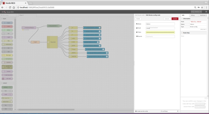
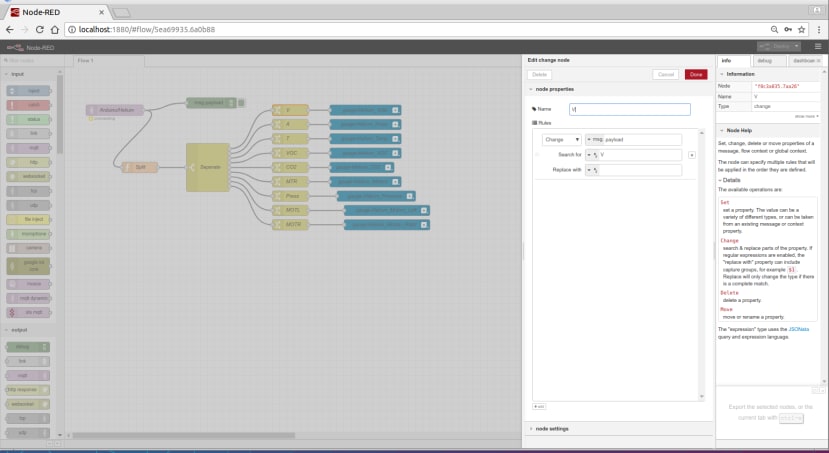
The following are screenshots from NODE RED. I am using this to separate the data and send it on.


Part 6: Putting it all together


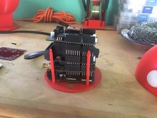
Now that you have the base done it is time to put the main wiring into the Orb and base. In the following series of pictures, I used silicone to secure the Arduino Base to the Orb Bottom.