Cargo Elevator electronic control
Follow article Dave from DesignSpark
How do you feel about this article? Help us to provide better content for you.
Dave from DesignSpark
Thank you! Your feedback has been received.
Dave from DesignSpark
There was a problem submitting your feedback, please try again later.
Dave from DesignSpark
What do you think of this article?
Nowadays, cargo elevators are used in lots of industries making workers life easier. We can find them in big factories, in construction sites, and even in restaurants with two floors. Most of cargo elevators have a single way of working: You push the button and it goes up or down to the end. However, the possibility to stop the elevator at any time and position could be of much help when a worker has to carefully place a fragile piece inside it.
This project tries to solve that problem mentioned before by means of the implementation of a cargo elevator electronic control with two different modes of operation.
- Automatic: Works like other cargo elevators.
- Manual: By using a potentiometer the worker can determine the position of the cargo elevator.
The project can be divided into three main parts:
- Circuit connections: the electronic control circuit is based on a Microchip® PIC16F877A microcontroller connected to different sensors and actuators described below
- Microcontroller programming: the microcontroller has been programmed in C using MPLAB integrated development environment.
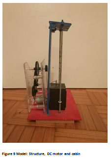
- Model fabrication: A small scale model has been also fabricated in order to test the proper function of the project. The model consists of three parts: The structure, a DC motor with a gear reducer chain and the mobile cabin.
The three main blocks mentioned above will be explained in more detail in the next sections.
Circuit Connections
In this block are explained all circuit connections and a brief explanation of the operation modules used. The project consist of some modules such as ultrasonic sensor, LCD screen, H Bridge, potentiometer and pushbuttons.
H Bridge
PIC outputs have not enough power to feed the DC motor so it is required to use a H bridge as it is shown in Figure 1. In this case, RB1 and RB2 pins from the microcontroller are used to activate or deactivate the four transistors of the H Bridge. RB1 is connected with S1 and S4. RB2 is connected with S2 and S3. H Bridge is powered with 5 VDC.

Ultrasonic sensor
The ultrasonic sensor detect the distance between the sensor and the mobile cabin. It is powered with 5 VDC too. RC1 is connected with echo and RC3 with trigger. A pulse is sent through trigger as it is shown in Figure 2. Then, the echo terminal sends a pulse with duration proportional to the distance of the object. The echo pulse is received through RC1 pin using rise and fall edge detection.

Potentiometer and pushbuttons
The pushbuttons are used in pull-up configuration. If it is not pressed, 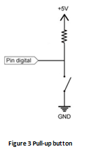
Potentiometer is connected to analog pin RA0. Analog-digital conversion result is used to calculate the distance at which the worker wants the cargo elevator to stop.
LCD screen
LDC screen is used to display the information about the operation mode. In manual mode it shows the value obtained from the potentiometer and in automatic mode it shows the position of the cargo elevator. LCD screen is connected to PORTD as it is shown in Figure 4 and it is controlled using the LCD control libraries and functions attached at the end of the article.

Control Program
The cargo elevator control program and the inputs and outputs are explained in this section. As it was mentioned before, the microcontroller has been programmed in C using MPLAB integrated development environment. The program code is attached at the end of the article.
Inputs/Outputs
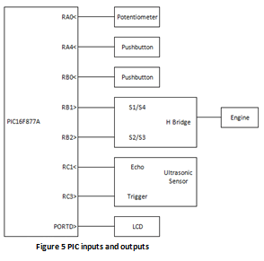
The inputs and outputs used are:
- RA0: As analogic input. Take potentiometer value. (ADC)
- RA4: As digital input. Order cargo elevator goes up and down.
- RC1: As digital input. Ultrasonic input. (CCP2)
- RC3: As digital output. Ultrasonic output.
- RB0: As digital input. Causes the interruption of mode change.
- RB1: As digital output. When pressed the cargo elevator goes up.
- RB2: As digital output. When pressed the cargo elevator goes down.
In Figure 6 is shown the model used on the lab. All connections can be seen on it.

Block Diagrams
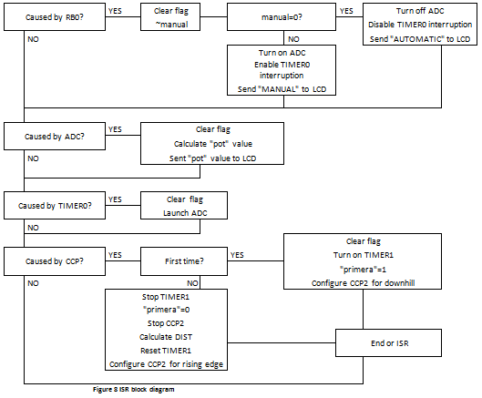
Cargo elevator program can be explained using block diagrams. There are two parts: Main program block diagram shown in Figure 7 and Interruption service routine block diagram shown in Figure 8.
Main program block diagram:

Interruption service routine (ISR) block diagram:
Model Design
In order to test if cargo elevator electronic control works, a model was made in the laboratory. Materials used on the model are wood and some steel pieces. These are cheap materials that can be bought in any hardware store. The design is very simple and it consists of 3 parts: the structure, the mobile cabin and a DC motor with a gear reducer chain.
- The structure: Is mostly made of wood with two steel bars used to guide for the cabin up and down.
- The mobile cabin: It is made of wood too but it has two steel pieces on the sides in order to attach the guides to the structure. It has also another steel piece on the top to tie a thread that goes to the DC motor helped by a pulley.
- The DC motor with a gear reducer chain: The gear reducer chain is made with plastic and it is linked with the DC motor using a timing belt.
Video
Cargo elevator electronic control works as shown in the following video.