Building custom capacitive interfaces with Electric Paint
Follow article
 Dave from DesignSpark
How do you feel about this article? Help us to provide better content for you.
Dave from DesignSpark
Thank you! Your feedback has been received.
Dave from DesignSpark
There was a problem submitting your feedback, please try again later.
Dave from DesignSpark
What do you think of this article?
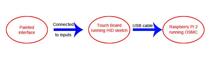
Using the Touch Board as a USB HID peripheral with the Raspberry Pi 2.
Pre-loaded with an Arduino sketch that plays audio instructions right from the outset, Bare Conductive's Touch Board is pitched as an easy-to-use platform for building interactive projects. Plenty of other example sketches are also provided, giving a great starting point for beginners.
Whilst it is possible to connect all manner of conductive materials to the Touch Board, it was originally designed to make it easier to build interfaces with Electric Paint. Based on the Arduino Leonardo, it has the ability to be used as a HID (Human Interface Device) – like a normal keyboard or mouse – to control any computer with a USB port.
This post looks at how we used the Electric Paint and Touch Board to build a giant touch controller for a Raspberry Pi-based media centre.
Configuring the Touch Board

To test the board simply connect power and headphones, and touch the terminals to hear the example MP3s. Should you wish to build something that just plays sounds, all you have to do is change the MP3 files on the SD card. However, to use the board in other ways, different sketches must be uploaded to it using the Arduino IDE.

Following the comprehensive instructions provided by Bare Conductive, we soon had the board connected to a Linux system running the latest version of the Arduino IDE (1.6.5 r5).
Next, the HID example code was uploaded to the Touch Board. It is worth noting that as soon as this is uploaded, the board will behave like a keyboard and 'type' letters when triggered.

As a test, a text editor window was opened and each electrode on the board touched in turn, soon filling the window with characters.

Notice from the code how the sensitivity of the touch inputs can be adjusted by changing two figures, setTouchThreshold and setReleaseThreshold. We found the default values worked well when simply touching the electrodes on the board.
Designing the Interface
With the basic functionality of the Touch Board tested, attention was turned to designing the interface. Since a durable finish was desired, we thought about how to keep the paint from being physically touched.
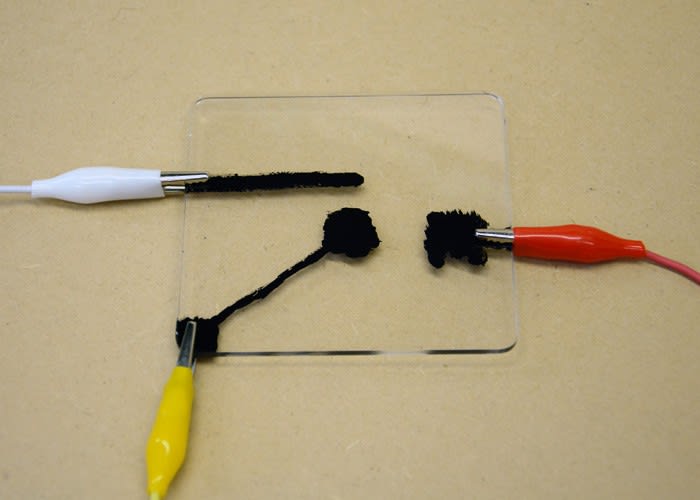
Paint was applied to one side of a 3mm thick piece of clear colourless acrylic, with the aim of detecting touch from the other side of the sheet. Once the paint had dried we used a crocodile clip lead to connect it to the Touch Board.
Using the default threshold values there was no touch detected through the acrylic, but changing the values of setTouchThreshold and setReleaseThreshold soon resulted in a working button.
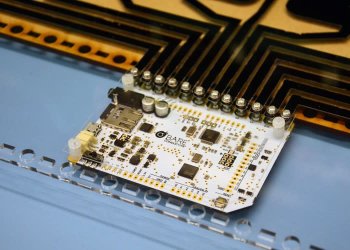
As the Touch Board has 12 electrodes that work as capacitive inputs, this is the maximum number of buttons or touch pads we could use for our interface. This meant that we had to control our Raspberry Pi media centre with a maximum of a dozen different keys!

The media playback software we used is OSMC (Open Source Media Centre) that is simple to install and use on the Raspberry Pi. With a slick GUI (Graphical User Interface), OSMC can be controlled by mouse or keyboard.
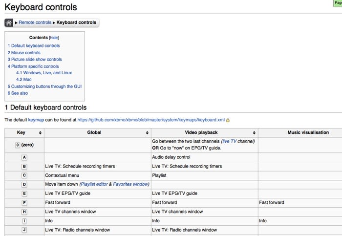
12 keys were chosen from the OSMC keyboard reference guide and added to the Arduino sketch, replacing the default keystrokes. Some keys were easy to define in the sketch, but for some – the plus and minus keys, for example – reference to an ASCII table was required.
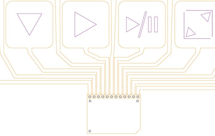
Once confident that OSMC could be controlled with 12 buttons a large interface was designed, with simple symbols depicting the functionality of each one.
Building the Interface

With basic testing and planning complete, the build could begin and a stencil was required to give a neat paint finish. We first thought of cutting the stencil from Mylar or MDF sheet, before realising that acrylic sheet comes with the perfect single-use stencil: the protective film coating already stuck to it!
Before cutting the acrylic sheet the button design was etched, with the protective backing left in place. Once etched and cut, the parts of the design to be painted were peeled off the acrylic, leaving behind the masking part of the stencil.

Electric Paint was applied to the prepared acrylic sheet. When the paint was dry the remaining backing sheet was removed, leaving behind the painted design.

Making the electrical connection between electrodes on the Touch Board and painted buttons on the acrylic came next. Each electrode has a hole large enough to fit an M3 machine screw, meaning that secure, reliable connections could easily be made. This is a great feature of the Touch Board and something we'd like to see more of on prototyping platforms.
Once attached to the acrylic sheet, more Electric Paint was used between the machine screws and painted tracks to avoid the possibility of any poor electrical connections.
Despite these machine screws holding the Touch Board to the acrylic sheet, the three additional mounting holes were also used to secure it in place.
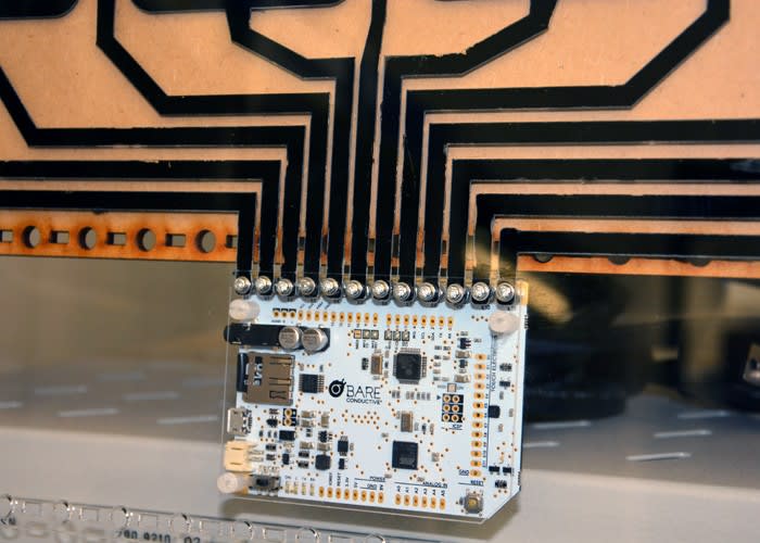
With the Touch Board mounted an MDF back-plate was added to protect the paint. Next the buttons were tested with the text editor again. Some more fine-tuning of the threshold values was required to give responsive and reliable control, as the larger painted areas did not function exactly the same as the original, smaller test.
Controlling the Pi
Installation and configuration of OSMC, though simple, is beyond the scope of this article. The instructions here were followed and we soon had a Raspberry Pi 2 set up and working.
The Pi was connected to a monitor, speaker, power supply and the Touch Board.
The video above shows the touch interface working with the media player – allowing for menu navigation, playback and volume control. No additional configuration of the Pi was required as the Touch Board simply behaves as a conventional USB keyboard.
Possible improvements could be to add LEDs or a buzzer to give some feedback when a button is triggered. These could be wired to a standard Arduino prototyping shield if headers are fitted, else directly to the inputs on the board.
A Powerful Platform for Custom Interactivity

The Touch Board is a great tool for building fun, unconventional interfaces very quickly. It's ability to act as a USB Human Interface Device is a fantastic feature, whereby modification of a simple Arduino sketch allows you to assign the touch inputs to different keystrokes to control unmodified applications, avoiding the need for modifying existing software and advanced programming skills.
The board also features an on-board connector for a LiPo battery and can charge this via USB power, making it convenient for building portable projects.
Coupled with the Electric Paint, the board really comes into it's own. We particularly enjoyed the novelty of painting the conductor, rather than cutting and soldering wires! It is easy to imagine an interactive surface on a much larger scale, or with a more abstract design than our set of buttons.
Rather than laser cutting some acrylic, it could be possible to add a layer of varnish or sticky back plastic over the paint to give a hard-wearing finish.
For further inspiration, check out some of the other examples of how people are using the Touch Board and Electric Paint on the Bare Conductive Make page.