Building a River Level Display – Part 1
Follow article
 Dave from DesignSpark
How do you feel about this article? Help us to provide better content for you.
Dave from DesignSpark
Thank you! Your feedback has been received.
Dave from DesignSpark
There was a problem submitting your feedback, please try again later.
Dave from DesignSpark
What do you think of this article?

Using a Raspberry Pi to Make a River Level Display
On boxing day there was severe flooding close to where I work. After seeing the impact this had on local homes and businesses, I really wanted to work together with my colleagues to produce something which might help in connection with flooding.
My colleague, Stuart, has installed a sensor developed by Flood Network which will remotely measure the level of the river outside our office.

Stuart installing the sensor
I decided to develop a display which would use LEDs to indicate the level of the river. This project is very similar to the Fabulous Festive Raspberry Pi Thermometer, however, instead of using the reading from a thermometer as the input, it will be using the readings obtained from the remote sensor instead. Hopefully this will raise awareness of when there is a higher chance to flooding associated with elevated water levels.
The data from the remote sensor will also be displayed via a web page, but the great thing about a physical display is that you don't need to go online to check the river level.
Design
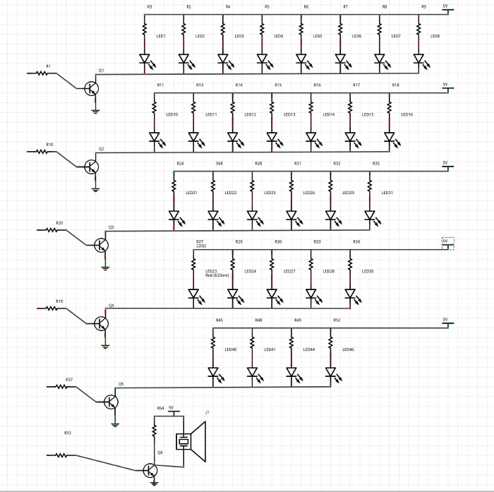
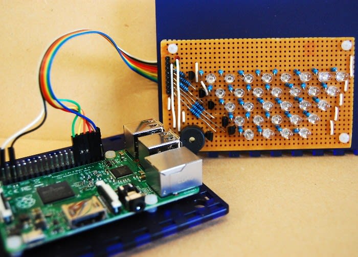
The Flood Aware monitor will be based on a Raspberry Pi 2 model B with a simple perfboard circuit, containing rows of LEDs to follow the shape of a river. Each row of LEDs will be switched by a BC337 transistor controlled by GPIO pins on the Pi.
After the schematic was completed I printed out a perfboard template so I could decide where exactly the LEDs and transistors would go and in what places I would have to break the copper tracks. This took a couple of attempts before I could get the layout right for the size of perfboard I wanted to use.
When I had completed the layout I placed the components and began soldering them in place. This was a bit fiddly with 30 LEDs, 37 resistors, 6 transistors,a piezo and a 6 pin header all on a relatively small perfboard. Some of the component legs needed carefully manipulating into place and I ended up breaking a couple of tracks in the wrong places. Luckily I managed to fix this by using some of the legs of components to replace the broken connections.

Prototype
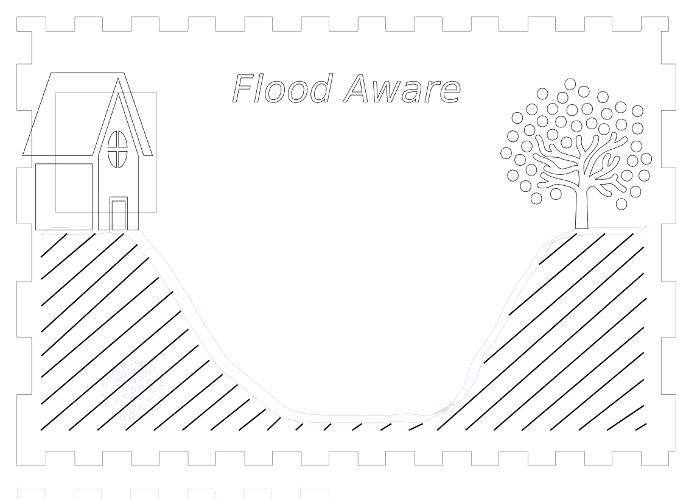
After I had completed soldering the components on the perf I then moved on to designing a case to house the Raspberry Pi and this. This was going to be made using frosted blue acrylic so that the LEDs would still be visible when illuminated inside the box. I started by designing what would be etched on the front and getting the dimensions for the placement of the LEDs and piezo.
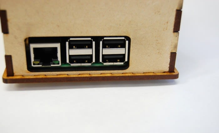
The enclosure would be made from four sides, a top, bottom and middle plate which would hold the perfboard in place. To hold all this together I used finger joints along the edges and put M6 bolts from the bottom to the top to secure it in place.
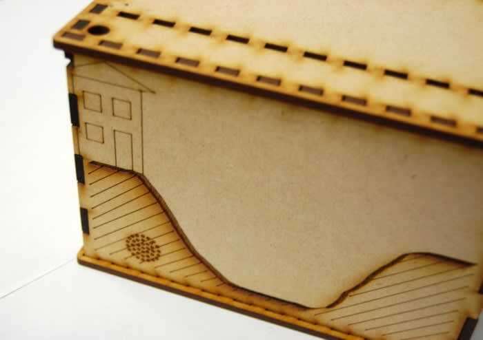
Once I had finished the design for the case in Inkscape I then proceeded by cutting a prototype of this in MDF. The first prototype had a couple of mistakes – some of the finger joints were slightly out so they didn't align properly. I had also made the holes ever so slightly too small so it was a really tight fit when it was pieced together. Another problem I encountered was that because I had designed it to take 70mm M6 securing bolts, everything inside was very close and again a very tight fit. I decided that this would be too close for comfort and that I would need to re-design this to eliminate any mistakes and to make the enclosure and finger joints larger.
Once the second prototype had been designed I then cut this in MDF and assembled it to check that everything fit. Unfortunately the back panel on this had some minor errors which meant this didn't fit due to the placing of the finger joints; however, the rest of the panels fit perfectly, so I amended the back panel and re-cut this in MDF. After this back plate had been re-cut the case fit together much better. I used 100mm M6 bolts this time and these coincided well with the overall size of the box. I was happy that this prototype would accommodate the Raspberry Pi and perfboard comfortably so I began to cut the enclosure out of acrylic.
Once this was cut from acrylic I assembled this to have one last check that everything was still aligned now that it was cut from a new material. As everything pieced together nicely I then used nylon hardware to mount the Pi and the perfboard. Each row of LEDs was then wired and connected via the 6 pin header to the GPIO pins on the Pi.

Modify
When it came to testing this I found a couple of issues. I had designed this based on the Festive Thermometer, using PNP transistors, where they would conduct when the base was pulled logic low and not when it was logic high. However, the LEDs in this were being supplied from 5V, therefore there would be a voltage difference between the base and collector of 1.7V with logic high (on a Raspberry Pi this is 3.3V).
I found when the board was powered and the GPIO pins were left in a floating state some of the rows were illuminated although not in full brightness and even when pulled logic high they would not turn off.

I decided that changing the transistors to NPN would work better as when the base is pulled high the LEDs will illuminate, which made much more sense to me. It took a little while to resolder the new BC337 transistors to the board as all the other components were so close together and I ended up needing some help from a colleague to do this without lifting the copper tracks. With a little help the perfboard now had new transistors and resistors to the base of these. There were also a few additional tracks on the perfboard which needed to be cut due to the different layout of the components.

Assemble
When these changes had been made I found that the board worked much better. I then took the time to test the piezo and figure out at what frequencies this worked best at. After this I reconnected the perfboard to the Pi and secured these to the enclosure using nylon hardware. Now I could begin programming!
Code
Initially I decided that just wanted to blink the LEDs so that I could thoroughly test the display. In another post I will cover extending this to connect to a server and retrieve the river level data.

One thing I stumbled across is when setting up the board is that if you use GPIO.setmode(GPIO.BOARD) this uses the physical pin out of the board you’re using, whereas if you use GPIO.setmode(GPIO.BCM) this means you are using the Broadcom SOC channel, which lets you use the GPIO numbers as your numbering scheme.
Below you can see the completed unit working as it is flashing each row of LEDs.
I'm looking forward to continuing working with it and connecting it to the river level sensor next time!