Building a Photo Booth Using a Raspberry Pi 4 and a Pi HQ Camera
Follow article
 Dave from DesignSpark
How do you feel about this article? Help us to provide better content for you.
Dave from DesignSpark
Thank you! Your feedback has been received.
Dave from DesignSpark
There was a problem submitting your feedback, please try again later.
Dave from DesignSpark
What do you think of this article?
Using a Raspberry Pi 4, HQ Camera and Touch Screen to create a custom photo booth for photography and videography.
This project builds on the experiments I have already made with the Raspberry Pi 4 and HQ Camera to build a photo booth I can use for recording future projects.
To start with I made a simple mount from laser cut MDF to hold the Pi, touch screen and HQ camera, and started thinking about making a version in acrylic so I could bend the section that held the lens so it would point down while the screen was at a convenient viewing angle.

I then realised I was, to some extent, re-inventing the wheel. I had already designed and built the Pidentifier enclosure which was a very similar design, so as I still had a prototype of the Pidentifier, I decided to re-purposed that for my new HQ Camera booth.

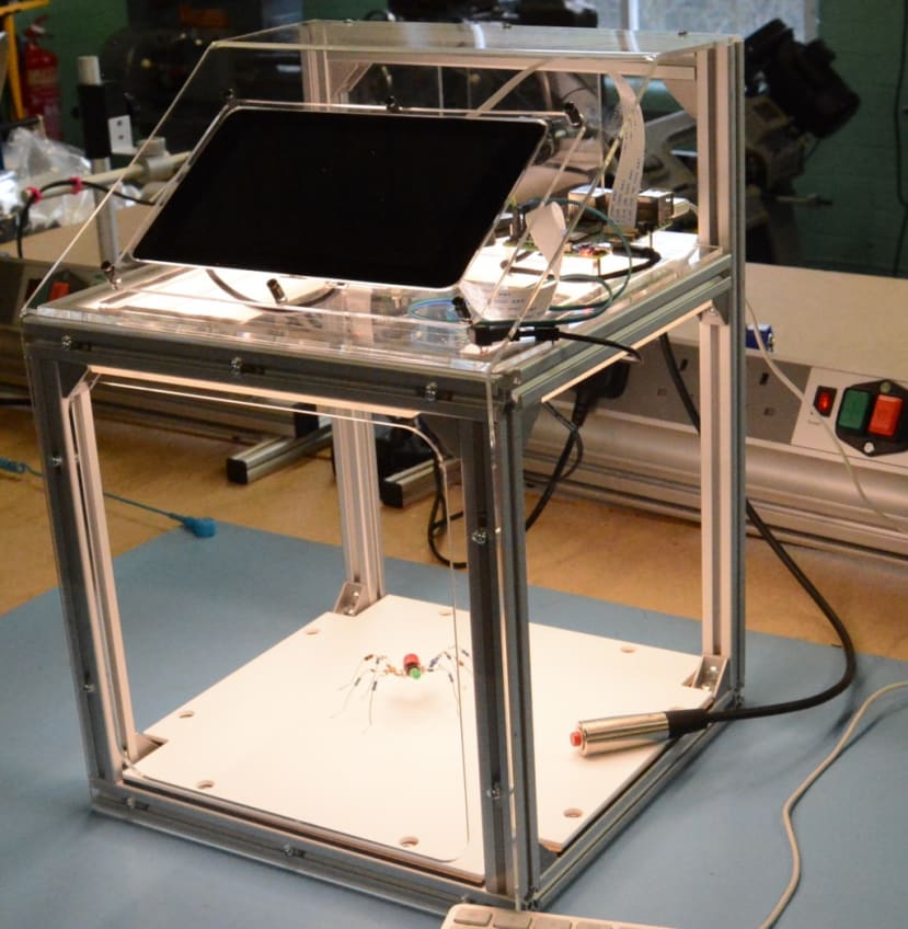
As you can see in the picture, it consists of a frame constructed from 2020 extruded aluminium (850-8476) . It has a clear laser cut acrylic front and top that is cut from a single sheet and then bent into shape.
The Raspberry Pi 4 (182-2096) is mounted on another laser cut piece of acrylic that is fixed to top section and connected with ribbon cables to the HQ Camera and touch screen. Strips of adhesive LEDs (786-9023) are fixed under this section. These require a 12V supply, so to save using a separate power supply for Pi and lights, I have used a small generic 12V to USB adapter that is also mounted in the top section and is powered by a 12V DC desktop power supply (172-0754) . This powers the Pi and the touch screen via their USB connectors.
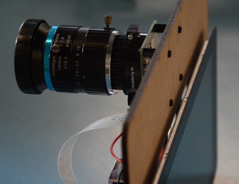
The one thing that I thought might pose a problem was the focal length of the lenses I had available. After trying different ones I found the best for the job was the CCTV one (776-9396) I had tried during my earlier experiments with the HQ Camera. As I detailed in that blog, the lens is a manual focus with a variable focal length that uses a DC drive auto iris. This means it needs supplying with between 1V and 4V to open the iris. I wrongly assumed that varying the voltage would vary the aperture (how open the iris is), but after some more reading on CCTV standard systems and trying out different voltages, it turns out it is either open or closed – nothing in between. So I did as I had done before and supplied the relevant pins on its connector with 3.3V from the Raspberry PI GPIO header.
Using the Cam Web Interface

Once the hardware was sorted out I needed a convenient way of triggering the camera. I installed the Cam Web Interface that I have used in previous projects and that I am a big fan of!
Initially I connected to the Camera’s web page that the software generates and which controls the camera from my PC, by entering the Pi’s IP address in a web browser. After a discussion with my colleague about how useful a camera GUI on the Pi’s touch screen would be, and after a quick search to see if I could spot any Pi software that would do this, I had a brain wave; I started up the Chromium web browser on the Pi, entered the IP address 127.0.0.1 in the address bar (127.0.0.1 is the loopback address), and there was the Cam Web Interface on my touch screen. I could make it more useable by starting Chromium in full screen mode from the terminal:
chromium-browser --start-fullscreen http://127.0.0.1/html/
That worked well, so I set it to run at start up using autostart by opening the autostart file using the Nano editor from Terminal by typing:
nano /home/pi/.config/lxsession/LXDE-pi/autostart
The added to the end of autostart file:
@chromium-browser --start-fullscreen http://127.0.0.1/html/
Then save and exit by typing CTRL x and selecting y.
I rebooted my Pi and it started with Chromium in full screen, displaying the camera web interface.
As a final tweak I set the preview width to 762, so that it fitted nicely on my touch screen. You can find this setting in the Preview Quality section of the RPi Camera Settings.
Alternative software
As an alternative to using the Cam Web Interface, and as a way of utilising physical buttons instead of the screen, I had a look at gpiozero, which is described as “a friendly Python API for physical computing”. The gpiozero documentation provides a whole load of what it describes as “recipes” for controlling things connected to the Pi’s GPIO header, including a few camera related ones.
Gpiozero is already installed on recent versions of Raspian, there was no need for me to do that.
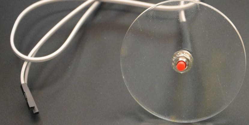
I made myself a cable release style button using a momentary single pole panel mount push button switch (133-6473) and a circle of acrylic. I connected this to and connected it to pin 3 and ground on the Pi’s GPIO header. The gpiozero library uses Broadcom (BCM) pin numbering for the GPIO pins, as opposed to physical (BOARD) numbering – luckily there is a clear diagram in the documentation labelling how the pins are numbered.
I used the following code to display a preview and then take a picture every time the button is pressed.
from gpiozero import Button

from picamera import PiCamera

button = Button(2)

camera = PiCamera()

camera.start_preview()

frame = 1

while True:

button.wait_for_press()

camera.capture('/home/pi/frame%03d.jpg' % frame)

frame += 1
The script imports the two libraries it needs, defines which pin is to be used, switches on the camera and then starts the camera preview. It then waits for the button to be pressed and captures a picture that it saves as frame001.jpg, and the next one as frame002.jpg, and so on.
At first the script would not run as I still had Cam Web Interface running in the background, so I needed to open its web page and stop the camera.
The script then ran successfully and saved an image every time I pressed the button. The only problem I had was getting out of the the full screen preview when I had taken all the pictures I wanted. Running it from a Python prompt I could have just pressed Ctrl and C, but for ease of use I had created a file called stop_motion.py and was running my script by executing that. I found another recipe that would close down the Pi when the button was pressed for 2 seconds – that was a bit drastic, so I adapted it to close the preview window with a long press of the button instead.
My script now looked like this:
from gpiozero import Button

from picamera import PiCamera

from signal import pause


button = Button(2, hold_time=2)

camera = PiCamera()


button.when_held = camera.stop_preview

camera.start_preview()


frame = 1

while True:

button.wait_for_press()

camera.capture('/home/pi/animation/frame%03d.jpg' % frame)

frame += 1
As well as adding the stop preview I have also edited the location for storing the images.
FFmpeg
Having taken a succession of pictures I used FFmpeg to make them into a stop frame animation. FFmpeg is a “complete, cross-platform solution to record, convert and stream audio and video. It is a powerful command line tool that allows you to process and edit all sorts of image files and it also comes pre-installed with Raspbian.
To convert my images to a film I simply typed the following in a terminal window:
ffmpeg-r 3-i animation/frame%03d.jpg -qscale:v2 spider.mp4
The “3” sets the number of frames per second,
“animation/frame%03d.jpg” tells it where to look for the imagefiles, -qscale sets size of each frame and “spider.mp4” specifies the name of the video file it produces.
I also found the FFmpeg options to add sound to my video:
ffmpeg -i video.mp4 -i audio.wav -map 0:v -map 1:a -c:v copy -shortest output.mp4
I used this to add a bit of sound that I had made on my modular synthesiser.
Conclusion
I now have a nice photo booth that will be a great way of recording future projects. It has two different options for running it.
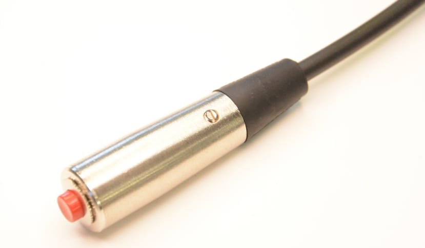
As a nice finishing touch I have upgraded my push button (878-7235) which now connects to the Pi via a 5 pin XLR plug (045-7914) and socket (045-7932) – the 5 pins giving me the option of adding more buttons to control additional functions in the future. I have cut a number of different bases to give me the option of white, black or grey backgrounds, and also an MDF one for documenting soldering. I think I may add some more LEDs for extra light.
I do like a project where I end up with something useful at the end and learn something along the way.