Building a Festive Rock 4 Powered Mechanical Organ Part 2: Assembly, Programming and Test
Follow article
 Dave from DesignSpark
How do you feel about this article? Help us to provide better content for you.
Dave from DesignSpark
Thank you! Your feedback has been received.
Dave from DesignSpark
There was a problem submitting your feedback, please try again later.
Dave from DesignSpark
What do you think of this article?

Designing an enclosure, constructing the organ and writing Python to play the recorders.
Introduction
In part one of this series we took a look at component choices to build a Rock 4 powered recorder organ that can play festive tunes. In this post we’ll be following the build process, taking a look at the Python code to control all the moving parts and then testing our hard work.
Design and Construction
Before we could place any components, we needed to decide upon a size for the frame that would form the enclosure. As the size is mainly dictated by spacing between the recorders and pneumatic cylinders, we laid these out on a bench to get a feel before taking measurements.

With suitable measurements decided upon, these were transferred into a CAD model where any last tweaks were made. To finalise the hole sizing that would seat the recorders, a number of test cuts were made at 0.5mm increments from 31 to 33 millimetres. A front plate was also designed that would hold the ten pilot lights indicating the status of each valve.
Height was decided based upon the height of the cylinders (where the body sits below the top plate) plus some extra “wiggle room” to allow clearance for pipework and cabling. Again, a similar methodology was used to decide upon the depth of the enclosure — enough to avoid collisions between components, without being excessively large.
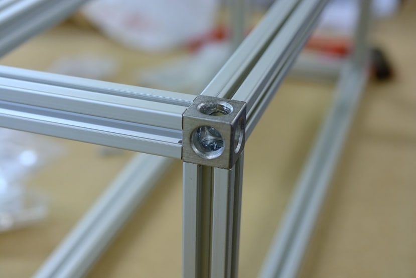
A cut list was produced using an online tool that finds the most efficient way to cut specified lengths. These were then cut and fastened together using Bosch corner cubes (466-7433) . The cubes are sold as a kit that contains three self-tapping screws and decorative covers that snap into the openings.

Eight sections of conduit were cut to a suitable length — again this was arbitrary based upon what would give clearance within the enclosure.
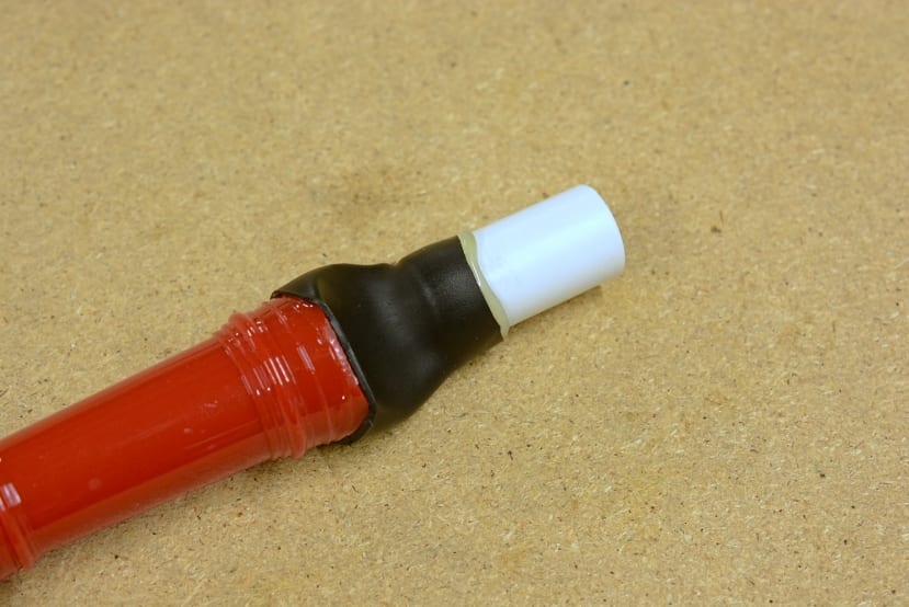
Hot-melt glue lined heat shrink tube was used to connect the recorders to the conduit. This ended up being somewhat finicky as the heat shrink tube would slide around when heated due to the glue melting, resulting in some glue seeping into the edge of the recorder mouthpiece.

M20 blanking plugs were purchased to connect the pneumatic push fitting to the conduit. These are designed to cover knock-outs in enclosures, but will also thread into common conduit fittings that use M20 threads.

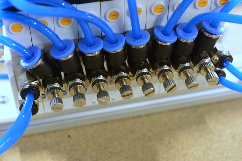
The ten solenoid valves were bolted together into an assembly using two M3 threaded rods. Each valve has interlocking features for horizontal stacking, as they can also be affixed to a manifold. Small acrylic feet were laser-cut and bent to mount the rack to the extrusion frame.

As the manifold already had mounting holes capable of accepting an M4 machine screw, these were bolted directly to the frame using T-nuts.

Hot-melt glue was used to retain the recorders. These are somewhat of a press fit but can freely flop forward and back due to the tapered shape of the mouthpiece, which is a problem that the glue solves.
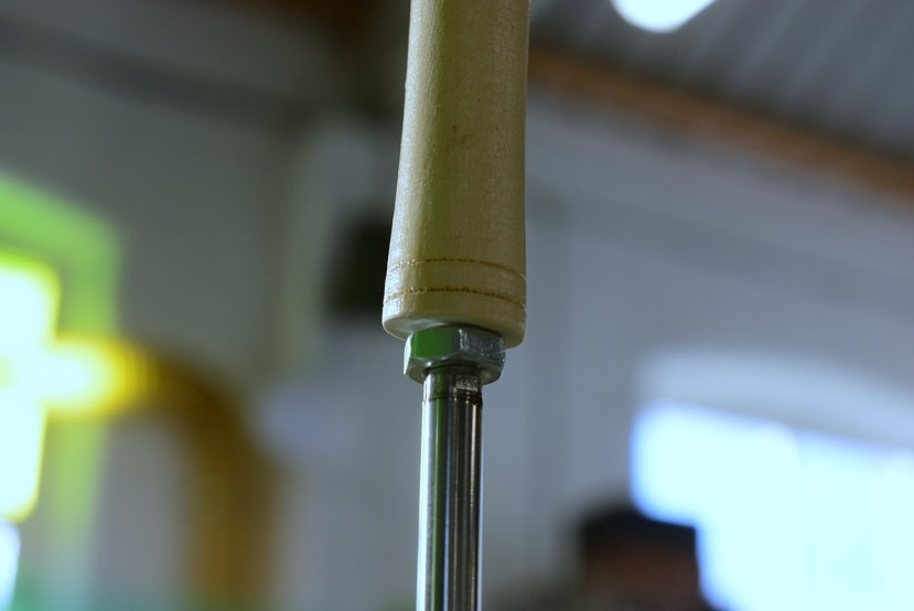
To affix the bells to the cylinders the end of the handle was cut off to a square edge, a hole drilled to slightly smaller than the major thread diameter and then screwed onto the cylinder rod.
With all the pneumatic components in place, we began the process of tuning each recorder. To get the desired note the recorder holes were covered with a small section of tape. Each flow control valve was then adjusted to produce maximum volume whilst maintaining a “pure” note — admitting too much air would set up nasty overtones and generally made a mess of the tone. Despite repeated attempts at carefully adjusting the valve for the F note, we could not get a clean note sound, which we chalked up to some glue entering the mouthpiece.

The last part to be assembled was the control box that contains the multi-channel power sequencer board, DC-DC converter and the Rock 4. We utilised the on-board WiFi of the Rock 4 for connectivity, although initial setup was done through an Ethernet connection. An off-the-shelf 5V, 3A DC-DC converter was used to save time designing and assembling another circuit board.
To finish assembly a cable harness was crimped up that would allow for the control box to be disconnected from the organ and we moved on to the Python script that would play a tune.
Python Control Script
Writing the Python to sequence all the valves on the organ turned out to be an easy affair, as we could repurpose most of the code we wrote last year.
The first step was to investigate talking to the PCF8575 GPIO expander over I2C, which required modifying a file /boot/hw_intfc.conf on the Rock 4 to enable I2C bus seven. A quick reboot later and the IO expander becomes visible at address 0x20; this was checked using the command i2cdetect -y 7.
To test operation of all the valves the command i2cset -y 7 0x20 0xFF 0x00 was issued, which instructs the GPIO expander to turn on the upper eight bits that are connected to our valves. A deafening noise emanated from the recorders, which was quickly stopped by issuing the same command with 0xFF swapped for 0x00.
Control of the GPIO expander in Python was realised through the use of the “pcf8575” module available on PyPI. This removes all the I2C interfacing leg work and exposes easy functions to set a pin level and also to read pins.
def warm_up():
	for p in pin_list:
		if p is not pin_bells:
			expander.set_output(p, True)
			time.sleep(0.3)
			expander.set_output(p, False)
			time.sleep(0.15)
The code first “warms up” the valves by toggling each one in succession. This is necessary as we found one of the valves would stick slightly, and a cycle before each use would help actuate it properly.
def all_notes_off():
	for p in range(0, 16):
		expander.set_output(p, False)
A helper function was written that would set all the valves off. This is necessary as sometimes we would observe the IO expander initialising into states with some pins on and some off.
jingle_bells = [
    (pin_e, 0.6),
    (-1, 0.05),
    (pin_e, 0.6),
    (-1, 0.05),
    (pin_e, 0.6),
    (-1, 0.6),

    ...

    (pin_e, 0.6),
    (-1, 0.05),
    (pin_d, 0.60),
    (-1, 0.05),
    (pin_g, 0.55),
    (pin_bells, 0.4),
]
We took our existing Jingle Bells note list and slightly modified it to have pin definitions and -1 for when nothing should be played. Timings were also slightly modified to make them sound more “correct” and to give the valves a better chance at actuating — it takes time for the valve to open, as the smaller pilot valve has to open which then opens the main part.
for note, duration in jingle_bells:
    if note == -1:
	all_notes_off()
    else:
	expander.set_output(note, True)

    time.sleep(duration * (60 / BPM))
Code for reading the note list was taken and adapted to instead set the appropriate GPIO pin high. This iterates over the list, pulling out each tuple that consists of the pin and a time to keep the valve open. If a -1 is encountered the function to turn all the valves off is called.
A ring of the jingle bells was added to the end of the song, at which point we tried the script to ensure everything worked — much to our amusement it did, including the dud “F” note.
During some further testing we noticed that one valve had a tendency to get stuck closed, so a quick script was written that would repeatedly toggle the valve pin rapidly to get the valve to unstick. This was not satisfying to run due to the noise produced once the valve began to move again.
Some further code hacking resulted in a just about passable rendition of Feliz Navidad being played, at which point we deemed the code complete and our objective achieved. Future improvements we’d like to try include making the Python code understand a MIDI file and use that to play the organ, rather than having a couple of badly transcribed songs.
It would also be nice to figure out why we sometimes have the odd sticking valve, which may be due to borderline supply pressure, flow rate or perhaps back pressure.
Demonstration Video
To Finish
In this post, we’ve taken a look at the construction of our mechanical recorder organ, including assembly of the valve rack, recorder mouthpiece adapters and control box. We then adapted our existing Python code to control a new piece of hardware and dealt with some of the challenges faced when running code that controls physical devices.