Building a Festive Rock 4 Powered Mechanical Organ Part 1: Getting Started
Follow article
 Dave from DesignSpark
How do you feel about this article? Help us to provide better content for you.
Dave from DesignSpark
Thank you! Your feedback has been received.
Dave from DesignSpark
There was a problem submitting your feedback, please try again later.
Dave from DesignSpark
What do you think of this article?
Attempting to design organ pipes using PVC conduit, settling for an alternative and then selecting the components.
Introduction
Around the festive period last year, we interfaced a USB-controlled stack light with Twitter to play (questionable) renditions of popular Christmas tunes when a Tweet was sent to our office tree.
This year, we wanted to try something that could possibly be even more fun — or annoying, depending upon where you stand on such things! — by constructing a self-playing organ out of recorders commanded by a Rock 4 C+.
Initial Investigation

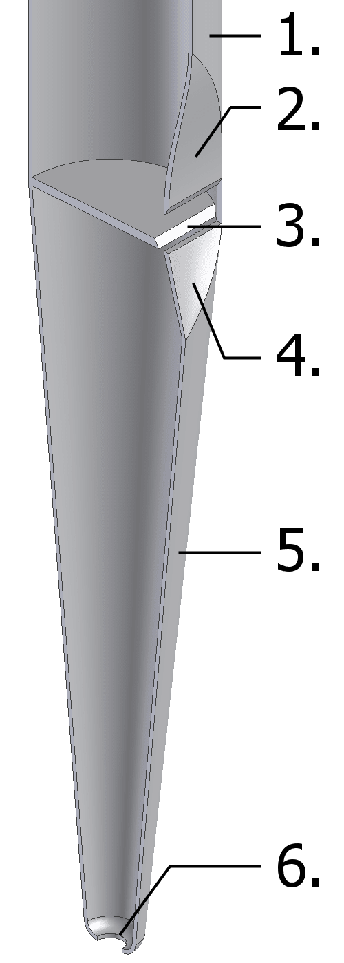
Organ pipes when viewed from afar look deceptively simple — a tube with a notch that produces a pleasing noise when air is admitted. However, the reality is that there is more going on than what meets the eye.
CC BY-SA 3.0, https://commons.wikimedia.org/w/index.php?curid=2350946
The design we wanted to try to mimic is commonly known as a “flue pipe” and is likely what comes to mind when discussing organ pipes. These function similarly to a recorder or whistle; fundamentally simple devices that rely on a stream of air that repeatedly creates and fills a vacuum (caused by Bernoulli’s principle), setting up a vibration within the resonator and producing sound.
To test whether a suitable pipe design could be produced using PVC electrical conduit, we started by watching a few YouTube videos where others had managed to create pipes. Watching these portrayed a simple process which required nothing more than filing a curve that tapered to a sharp edge into the side of a section of pipe, then constructing a “baffle” to direct airflow towards the edge.
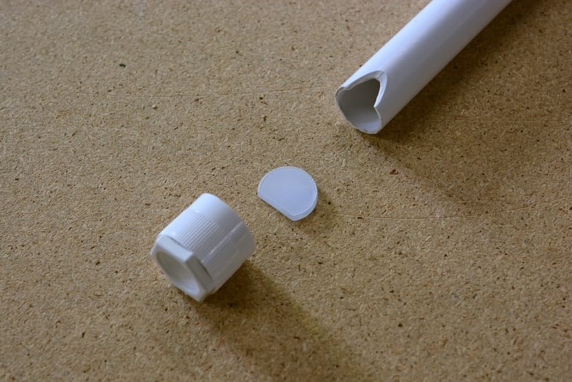
We attempted this using a length of conduit and a laser cut baffle with a fairly arbitrary size, inserted into a conduit coupler that was a snug press fit. Air was blown into the end of the conduit which produced nothing more than an awful, high pitch screech — no good for an organ.
Further testing was conducted by swapping the short conduit section for a significantly longer one, in the hope that the increased length would reduce the frequency of the tone. Unfortunately, this didn’t work as the note produced was still the same high pitch screech.
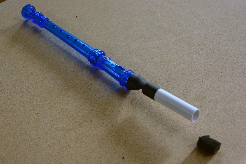
Our last resort was to buy an off-the-shelf recorder and figure out a way to connect a pneumatic tube to the mouthpiece. We settled on using a section of heat-shrink tube shrunk around the mouthpiece and a length of conduit to which a pneumatic fitting would be attached.
This was tested using a blow gun attached to our workshop air line at only a few pounds per square inch of air pressure. This worked satisfactorily, but one caveat was the directed jet of air occasionally could produce what sounded like harsh overtones. An easy work-around was to insert a small piece of foam into the conduit that acted as a diffuser, providing a nice even airflow into the recorder. Some form of flow control will be required as we observed that a too high flow rate again produced an ear-piercing screech.
With a proof-of-concept, we moved onto component selection to build the control system.
Component Selection

Perhaps the most vital part of our organ are the recorders. We selected eight identical recorders in red and green, in keeping with our festive theme. These can be disassembled for cleaning, which in our case is a non-issue as we’re using compressed air rather than moist breath.
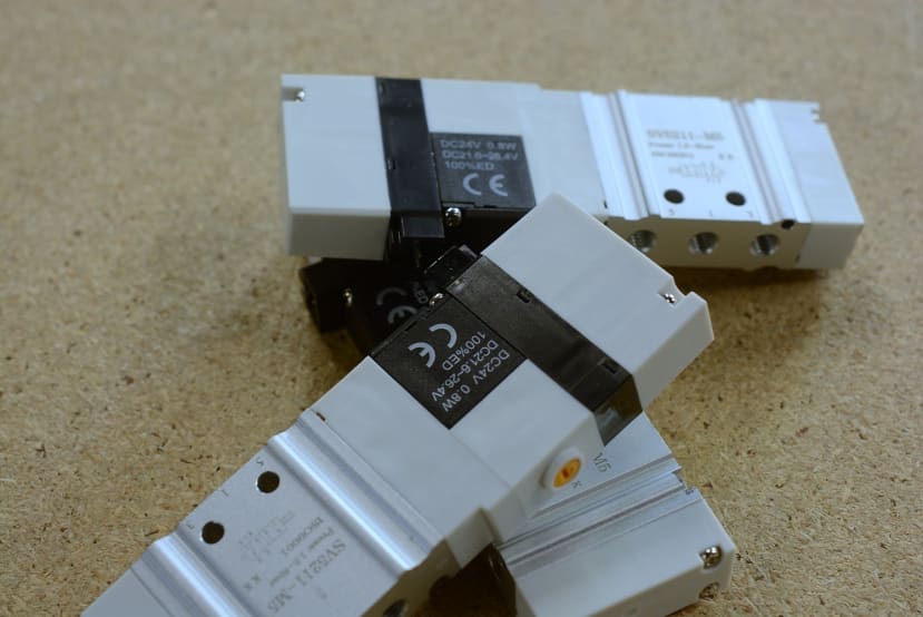
5/2 solenoid valves (235-1281) were chosen to control air flow to the eight recorders. These valves operate at 24V and have a low minimum operating pressure, although in this application the low operating pressure is not an issue.
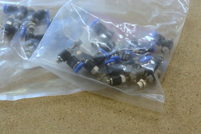
M5 threaded speed controllers (144-2657) were purchased to regulate the flow of air into the recorders, which permits individual fine adjustment. These were also required as otherwise the minimum operation pressure of the solenoid valves would allow too much air into the recorders, producing shrill noises as discovered earlier.
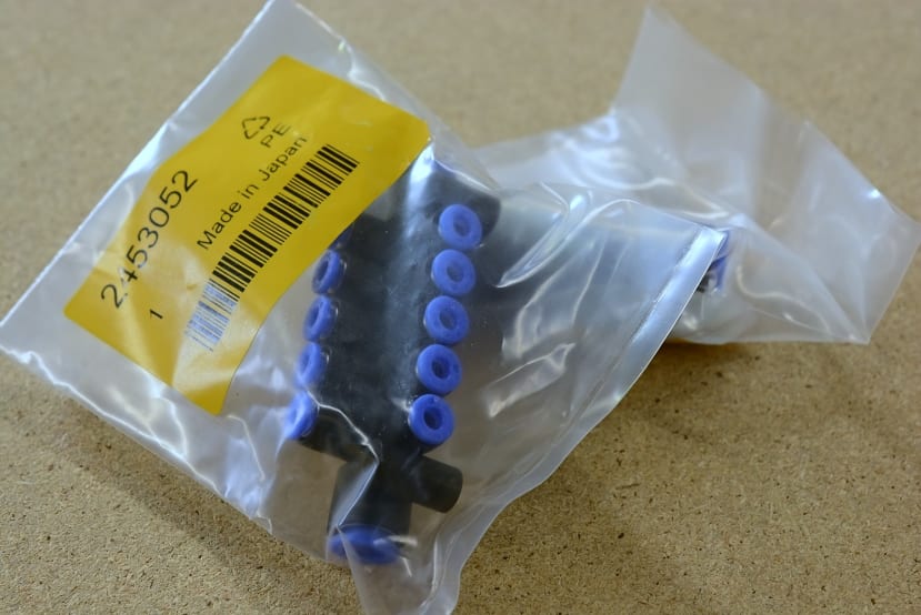
Given there are a number of pneumatic connections to be made including ten solenoid valves, two manifolds (245-3052) were purchased. These present two 8mm diameter tube connections and fan out to eight 4mm tube connections. To accompany the manifolds a pack of five 8mm blanking plugs (218-1785) were purchased to cap the unused end.

For added novelty, two pneumatic cylinders (304-3577) were selected with the intention of having sleigh bells fitted to add additional musical elements to a composition. We did think about adding an air horn, but deemed that slightly too ridiculous — even by our standards.
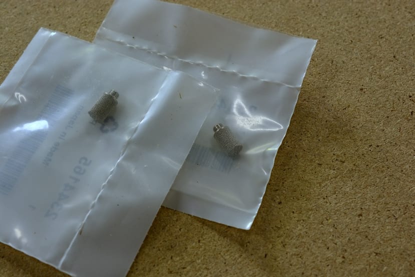
To minimise noise from the cylinders venting when the solenoids are actuated, a pack of M5 threaded silencers (234-4165) were selected. These work by passing the exhaust air through a sintered matrix that diffuses and slows down the stream of air, reducing the noise produced.
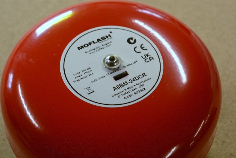
Adding to the collection of noise making devices is a 24Vdc solenoid-actuated bell (901-0703) . This was chosen over a motor actuated version in the hope that the solenoid would give us better control; we can quickly pulse the solenoid to get one or two rings, whereas a motor would need to spin up and down to produce any ringing.

To provide control signals to all the solenoids we will use one of our Multi-channel Power Sequencer boards that we developed for an RS Pro demonstrator build. This features eighteen MOSFET output channels that can be operated at either 12V, or 24V with small modifications.

Since we did not want to control the power sequencer with a Raspberry Pi Pico a drop-in replacement board was designed. This plugs into the Pico socket, relying on the I2C expansion header on the sequencer for external connectivity. A PCF8575 16-bit I2C GPIO expander then provides the control signals to switch the MOSFETs.

Commanding the system is a Rock 4 C+ (249-3158) single board computer. Packing an impressive list of features including a hex-core ARM CPU (dual Cortex A72 cores clocked at 1.5GHz and quad Cortex A53 cores clocked at 1.0GHz) paired with 4GB LPDDR4 RAM, dual micro-HDMI outputs capable of up to 4K60 resolution, two USB 2.0 and one USB 3.0 host port, plus another dual-role USB 3.0 host/OTG port, gigabit Ethernet, MIPI CSI and DSI ports and forty user GPIO.
Debian, Ubuntu and various versions of Android are all supported with pre-built images provided by Radxa. A number of third-party images are also available including Armbian, LibreELEC, FreeBSD and more.
Of interest are the two I2C buses present on the GPIO header, one of which we’ll be using to control the GPIO expander from a Python script to sequence the valve activation.

To provide additional “eye candy” a number of white LED pilot lights (763-7905) were selected. These feature a clear lens on the front that can be unscrewed and we planned to use this to add a small printed acetate sheet that displays the note each recorder would play.
Rounding out the component selection consisted of an assortment of additional parts, including aluminium extrusion (466-7219) and suitable connecting components, a variety of connectors (144-4220) to construct a wiring harness, power supplies and assorted discrete components to assemble the sequencer board.
To Finish
In this post we’ve taken a look at some of the theory behind organ pipes and how they work, had an attempt at constructing our own pipes before settling on using off the shelf recorders, and then looked at the remaining component choices.
Part two in this series will cover construction of the frame and cabling all the components together, writing the Python script and testing of the organ.